Inter-M PAM-520 User Manual
Page 11
8
PAM-510/520
ATT. ZONE AMPLIFIER
13. REMOTE CONTROL INPUT
By connecting a 15-pin D-SUB connector, it is possible to control speaker zone selection and activate the
chime via wired remote. Connection terminals for the remote are shown below.
14. AMP IN
This input connects an external mixer or preamp with the unit’s power amp. Inserting a plug into the Amp In
jack will disconnect all input signal from the unit’s internal mixer. Only signal from the external source will be
heard.
15. PRE OUT/REC OUT
This output connects the unit with an external devices such as tape recorders or power amplifier.
(OUTPUT LEVEL: REC OUT: -10dB, PRE OUT: 0dB )
16. LINE INPUT CHANNEL 1~2
This line-level input is an extra stereo input for a stereo source such as a tape deck or CD player.
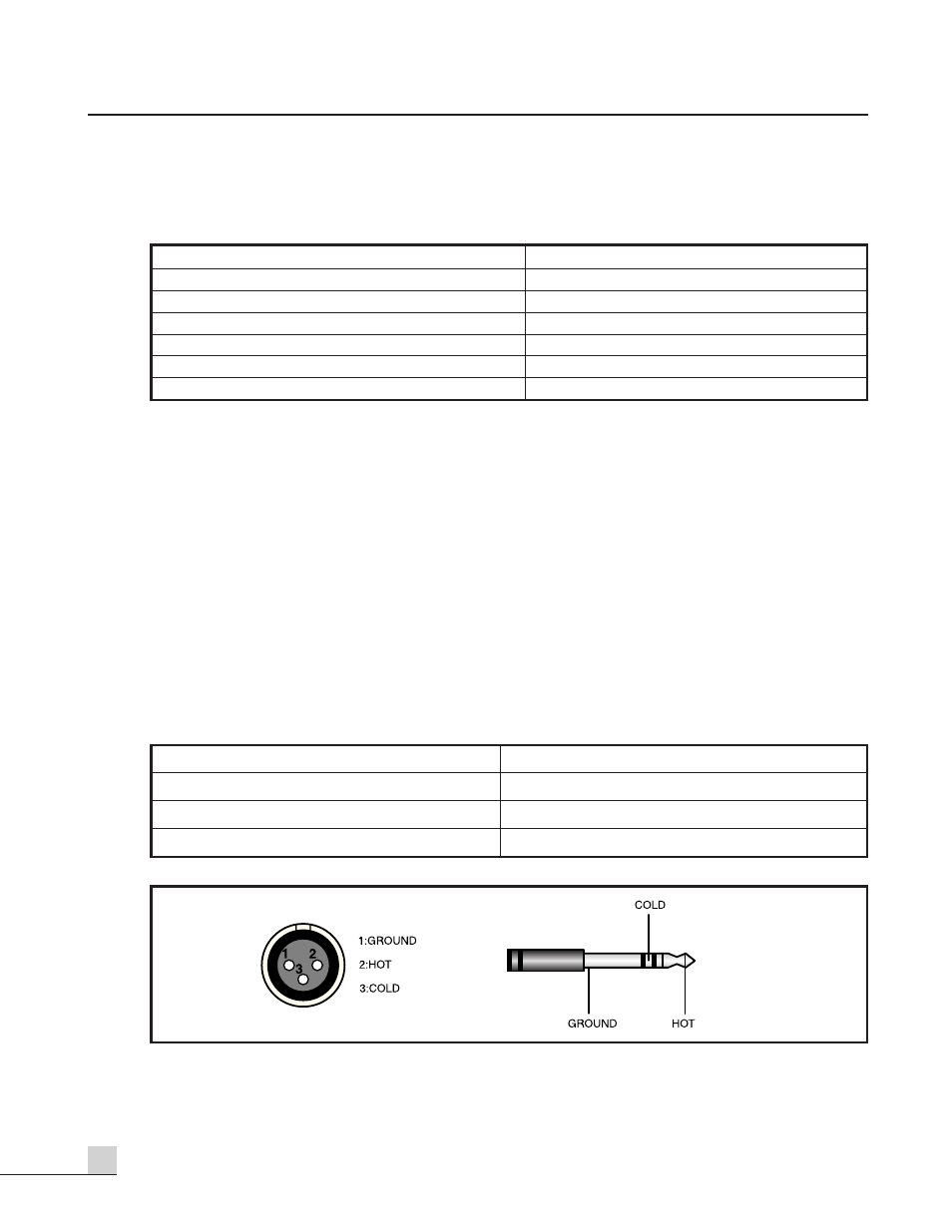
17. MIC INPUT CHANNEL 1~4
This is a special connector which will accept either a 3-conductor XLR or a 3-conductor 1/4” jack. These
inputs are suitable to receive signal from microphones level devices.
Pin 1: Remote amplifier input signal hot(+)
Pin 8: Remote control 5(Speaker 5)
Pin 2: Remote amplifier input signal cold(–)
Pin 9: Remote control ground
Pin 3: Signal ground
Pin 10: DC +24V
Pin 4: Remote control 1(Speaker 1)
Pin 11: Input Chime
Pin 5: Remote control 2(Speaker 2)
Pin 12: NC
Pin 6: Remote control 3(Speaker 3)
Pin 13: NC
Pin 7: Remote control 4(Speaker 4)
Pin 14, 15: NC
MIC JACK (XLR JACK)
LINE JACK (TRS PHONE JACK)
Pin 1: GROUND
Sleeve: GROUND
Pin 2: HOT(+)
Tip: HOT(+)
Pin 3: COLD(–)
Ring: COLD(–)