Transmitter front panel – Inter-M ITX-108 User Manual
Page 6
2/8 CHANNEL AUDIO TRANSMITTER/RECEIVER
4
FTA-108S/ITX-108/ITX-102, FRA-108S/IRX-108/IRX-102
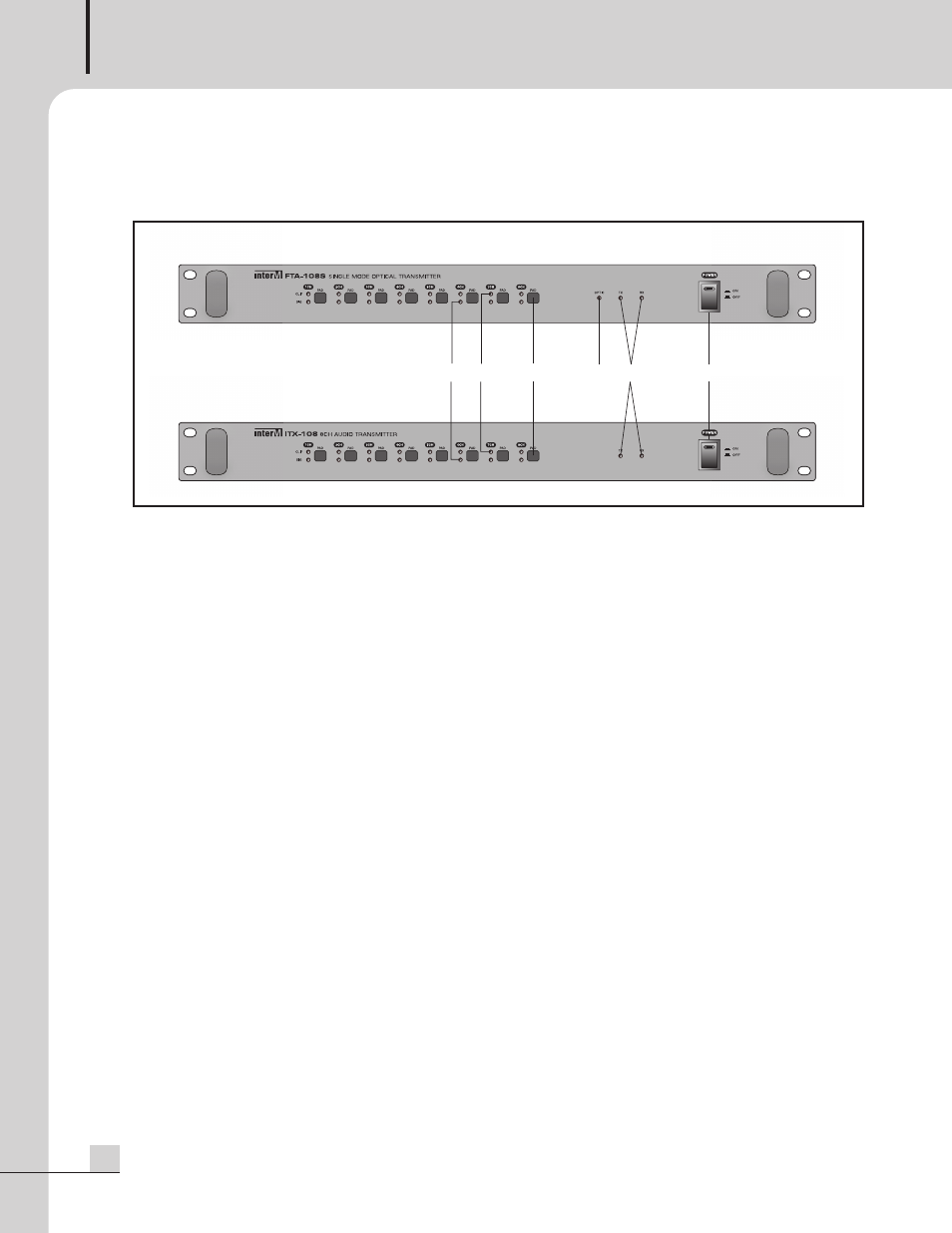
Transmitter Front Panel
Transmitter Front Panel
(FTA-108S/ITX-108/ITX-102)
1. INPUT SIGNAL DETECTING DISPLAY
Displays the input signal levels sending to each channel and green light will be on if -30dBV or higher is
supplied.
2. INPUT SIGNAL CLIP DISPLAY
Displays the clip status of input signal sending to each channel and red light will be on before signal clip.
3. PAD SWITCH
Pad switch to control the input level of each channel, and if signal clip occurs, push the signal to decrease
the input signal in 10dB to control the input level.
4. OPTICAL CABLE CONNECTION INDICATOR (FTA-108S)
Displays the connection of optical cable. Green light will be on if connection is normal and will be off if error
occurs on the connection.
5. DATA COMMUNICATION STATUS DISPLAY
If communication module (CT-100M) is installed, it displays the TX/RX data communication status of RS-
232C/RS-422.
6. POWER SWITCH AND INDICATOR
If this switch is pushed, power indicator will be on and equipment will be started.
1
2
3
4
5
6
FTA-108S
ITX-108