D. scalding, E. temperature and pressure relief valve – HTP SSC-119 User Manual
Page 9
9
LP-65 Rev. 3.24.14
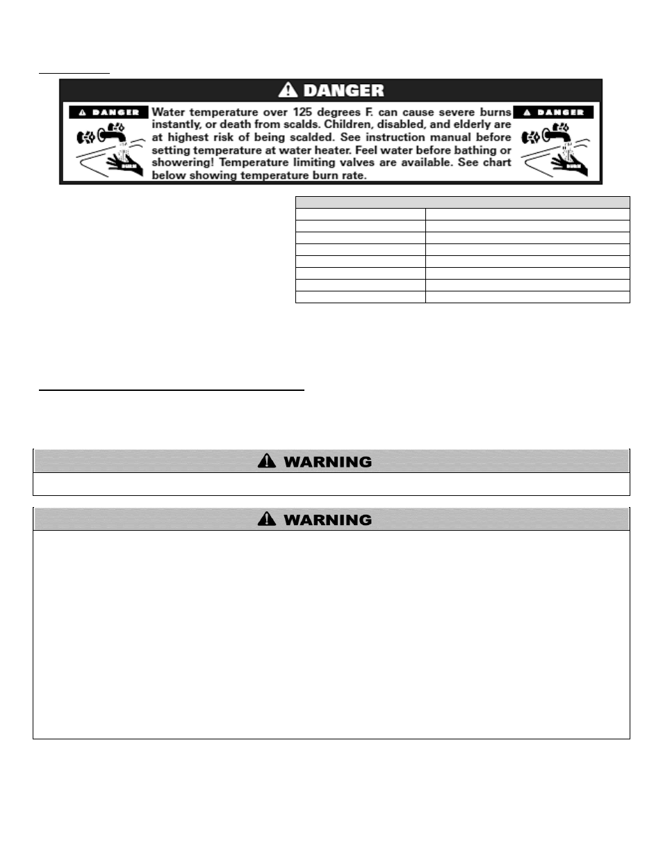
D. SCALDING
This heater can deliver scalding water. Be careful
whenever using hot water to avoid scalding injury.
Certain appliances, such as dishwashers and automatic
clothes washers may require increased water
temperature. By setting the thermostat on this heater to
obtain the increased water temperature required by
these appliances, you may create the potential for scald
injury.
To protect against injury, you should install a mixing
valve in the water system. This valve will reduce point of
discharge temperature by mixing cold and hot water in branch supply lines. Such valves are available from your local plumbing supplier.
Table 2 details the relationship of water temperature and time with regard to scald injury and may be used as a guide in determining the
safest water temperature for your applications.
E. TEMPERATURE AND PRESSURE RELIEF VALVE
A factory installed temperature and pressure relief valve long element, meeting the requirements for relief valves for hot water heaters
ANSI Z21.22B / CSA 4.4-M99, has been installed for your safety and convenience. If servicing, make sure that the relief valve is sized
to the BTU/hour capacity and storage capacity of the water heater. If the relief valve weeps, see expansion tank section for
suggestions.
Do not thread a cap or plug into the relief valve under any circumstances! Explosion and property damage, serious injury, or death may
result.
To avoid water damage or scalding due to relief valve operation:
Discharge line must be connected to relief valve outlet and run to a safe place of disposal. Terminate the discharge line in a
manner that will prevent possibility of severe burns or property damage should the relief valve discharge.
Discharge line must be as short as possible and the same size as the valve discharge connection throughout its entire length.
Dis
charge line must pitch downward from the valve and terminate at least 6” above the floor drain, making discharge clearly
visible.
The discharge line shall terminate plain, not threaded, with a material serviceable for temperatures of 375
o
F or greater.
Do not pipe discharge to any location where freezing could occur.
No shutoff valve may be installed between the relief valve and heater or in the discharge line. Do not plug or place any
obstruction in the discharge line.
Test the operation of the relief valve after filling and pressurizing the system by lifting the lever. Make sure the valve
discharges freely. If the valve fails to operate correctly, immediately replace with a new properly rated relief valve.
Test T&P valve at least once annually to ensure th
e waterway is clear. If valve does not operate, turn the heater “off” and call
a plumber immediately.
Take care whenever operating relief valve to avoid scalding injury or property damage.
FAILURE TO COMPLY WITH THE ABOVE GUIDELINES COULD RESULT IN FAILURE OF RELIEF VALVE OPERATION,
RESULTING IN POSSIBILITY OF SUBSTANTIAL PROPERTY DAMAGE, SEVERE PERSONAL INJURY, OR DEATH.
APPROXIMATE TIME / TEMPERATURE RELATIONSHIPS IN SCALDS
120
o
F
More than 5 minutes
125
o
F
1 ½ to 2 minutes
130
o
F
About 30 seconds
135
o
F
About 10 seconds
140
o
F
Less than 5 seconds
145
o
F
Less than 3 seconds
150
o
F
About 1 ½ seconds
155
o
F
About 1 second
Table 2