Part 4, Heater control and wiring, A. control – HTP SSC-119 User Manual
Page 16: B. wiring, Part 5, Operating the heater, Part 6, Maintenance and troubleshooting, Part 4 – heater control and wiring, Part 5 – operating the heater
16
LP-65 Rev. 3.24.14
PART 4 – HEATER CONTROL AND WIRING
A. CONTROL
A surface mounted control is provided and mounted inside of the control access compartment. There is an insulation blanket under the
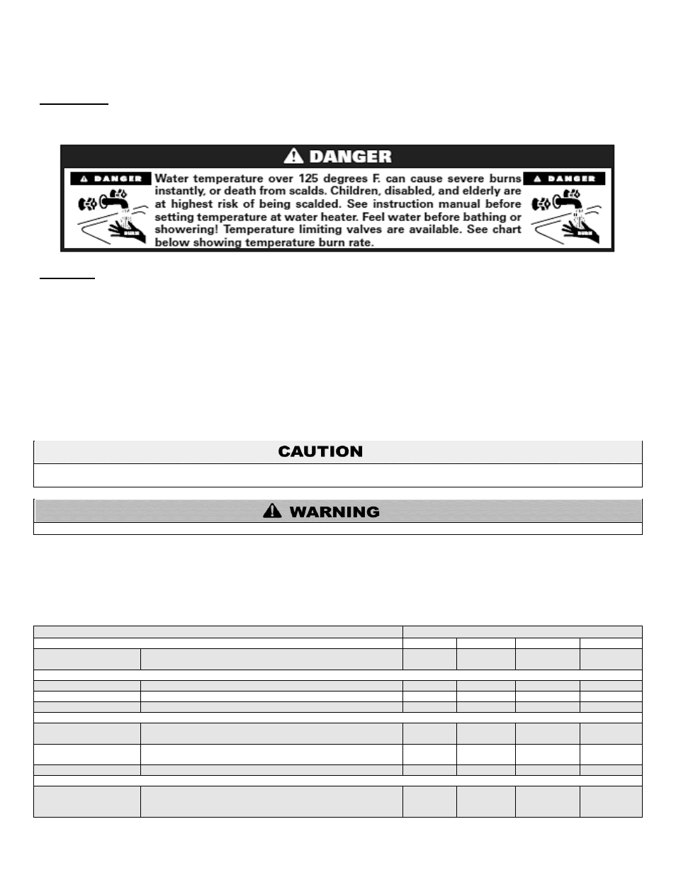
control access cover to ensure accurate readings of water temperature. The control is factory set at 120
o
F for your safety (see scald
danger warning below). The differential is fixed at 3
o
to 5
o
(not adjustable).
B. WIRING
Wiring is to be done in accordance with all applicable local and state codes. Turn off all power related to the boiler starting and wiring
procedures. It is recommended that a disconnect switch be installed between the boiler control and water heater.
PART 5 – OPERATING THE HEATER
Boiler high limit should be at least 20
o
F higher than the heater temperature. Set the low limit of the boiler control at the minimum setting
– this will call the burner on to satisfy the tank control.
We recommend a water heater temperature setting of 120
o
F. However, a lower temperature setting may be required to comply with
local and state codes for normal operation. The differential is fixed at 3
o
to 5
o
. You may prefer a setting of either higher or lower water
temperature. A mixing valve in conjunction with a high temperature setting may be used for high demand applications (spas, hot tubs,
whirlpools).
If draining of the heater is necessary, open the temperature and pressure valve or a hot water tap to prevent vacuum buildup in the tank
and piping.
Risk of scald injury increases as you increase water temperature.
PART 6 – MAINTENANCE AND TROUBLESHOOTING
Periodic maintenance should be performed by a qualified service technician to assure that all the equipment is operating safely and
efficiently. The owner should make necessary arrangements with a qualified heating contractor for periodic maintenance of the heater.
Installer must also inform the owner that the lack of proper care and maintenance of the heater may result in a hazardous condition.
INSPECTION ACTIVITIES
DATE LAST COMPLETED
PIPING
1
st
YEAR
2
nd
YEAR
3
rd
YEAR
4
th
YEAR*
Near heater piping
Check heater and system piping for any sign of leakage; make
sure pipes are properly supported.
SYSTEM
Visual
Do a full visual inspection of all system components.
Functional
Test all functions of the system
Temperatures
*Verify safe settings on Anti-Scald Valve
ELECTRICAL
Smoke and CO
detector
*Verify devices are installed and working properly. Change
batteries if necessary.
Circuit Breakers
Check to see that the circuit breaker is clearly labeled. Exercise
circuit breaker.
Connections
Check wire connections. Make sure they are tight.
ANODE ROD
Remove and visually inspect the anode rod. Anode rod should
be replaced when more than 6” of core wire is exposed at either
end of the rod.