Part 7 servicing, B. adjustment set points and differential settings – HTP Munchkin High Efficiency Heater User Manual
Page 14
PART 7
SERVICING
7-A. SEQUENCE OF OPERATION
1. When power is first applied to the control, the control will initially run through a self-diagnostic routine and then go
into its operating mode. If there is no call for heat, the System will go into the idle state.
2. If the thermostat is calling for heat, the control will apply power to the circulator pump. If the control determines the
appliance water temperature is below the programmed set point value less the switching dif ferential, the control will
initiate a heating cycle.
3. The control then performs selected system diagnostic checks. If all checks are successfully passed, a pre-pur ge cycle is
initiated (blower on max speed).
4. When the pre-purge period is complete, power is applied to the spark ignitor for approximately 6 seconds.
Approximately 2 seconds later, we verify flame. If a flame is not verified during the trial-for -ignition, the gas valve is
immediately closed and the control will return to step 2. If after three trials a flame is not verified, the control will go
into lockout mode. If a flame is confirmed, the control enters the heating mode. Fire rate based on the proprietary
algorithm.
5. When water temperature reaches the temperature set point valve plus 10 degrees F (or if the thermostat call-for -heat is
satisfied), the gas valve is closed and the control enters post-pur ge (blower on max speed). NOTE: IF THE
THERMOSTAT IS STILL CALLING FOR HEAT, THE CIRCULATOR PUMP WILL CONTINUE TO RUN
UNTIL THE THERMOSTAT CALL FOR HEAT IS SATISFIED.
6. When post-purge is complete, the control enters the idle state while continuing to monitor temperature and the state of
other system devices. If a call-for-heat is received, the control will automatically return to step 2 and repeat the entire
operating cycle.
During the idle state and heat state, if the control detects an improper operating state for external devices such as the high-
limit switch, the green LED on the control will flash an error code sequence.
7-B. ADJUSTMENT SET POINTS AND DIFFERENTIAL SETTINGS
1. Temperature Adjustment- A potentiometer located on the control board is used to adjust the set point temperature on
the boiler appliance. This can be set between 70 and 210 degrees.
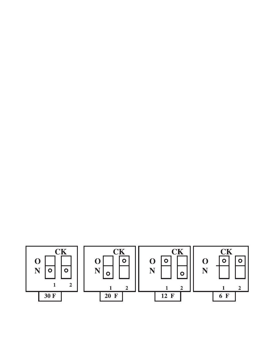
2. Temperature Differential Adjustment - A "DIP" switch is located on the control board. Depending upon the
configuration of the "DIP" switch, the dif ferential selection is 6, 12, 20, or 30. See the figure below for further detail.
NOTE: the differential adjustment is the value below the set point, when the burner will fire. (Example: 190 degree set
point, 30 degrees differential, burner will not fire until return water drops below 160 degrees and will modulate the flame until
190 degrees is reached, then post purge and idle state will be achieved. If at any point TT is satisfied, the cycle will be
interrupted by post purge and idle state.
12