Hochiki FIRElink-25 User Manual
Page 30
Page 30 of 40
FIRElink-25 – Installation Manual
© 2010 Hochiki Europe (UK) Ltd
9-5-0-344/ISS4/OCT10
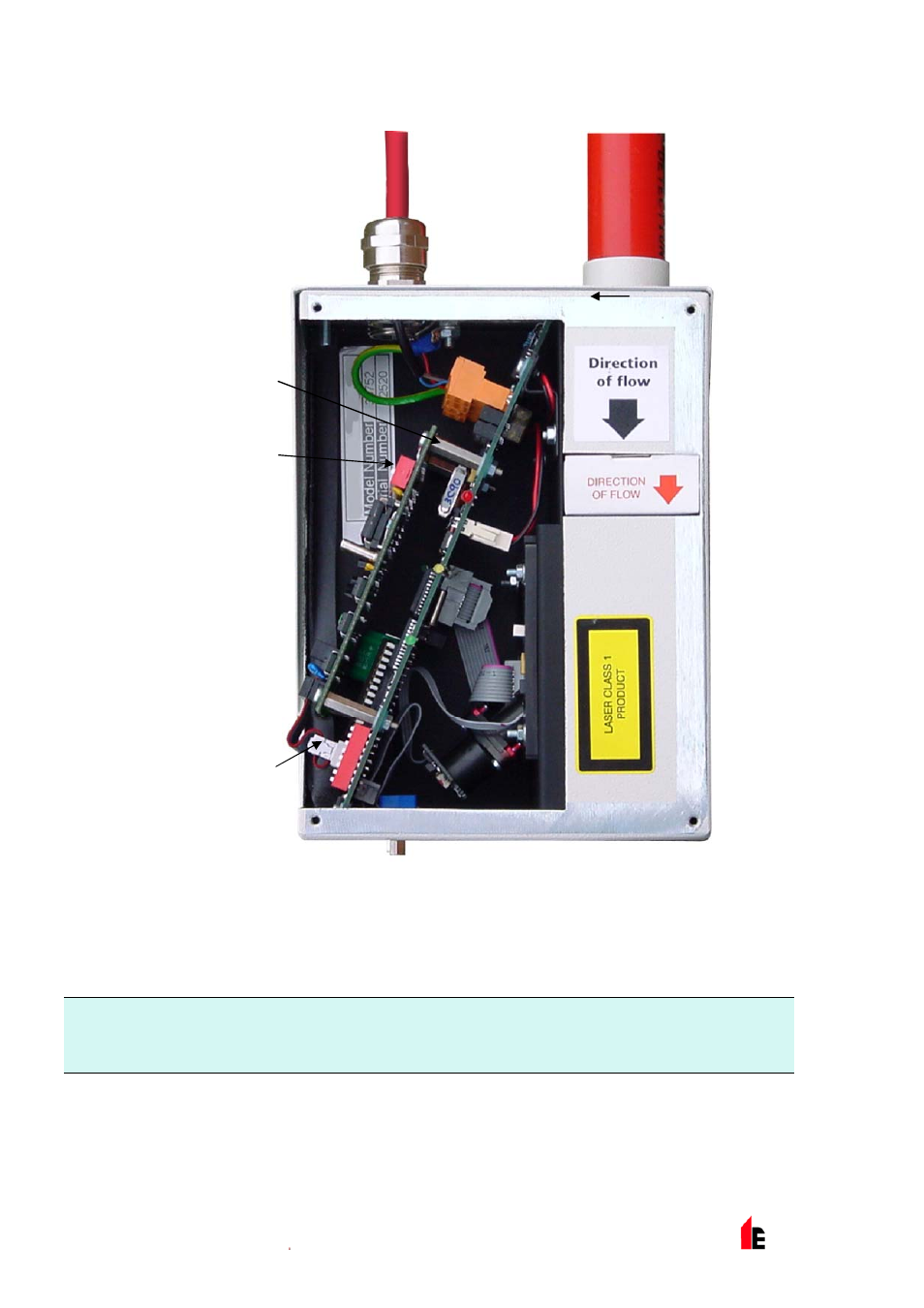
FIRElink-APIC
Mounting Studs
FIRElink-APIC
Address Switches
(x 2)
FIRElink-APIC
Interface
Connection
The connections to the Fire Panel are made using the BUS L1 and H1 (bus 1 input and output) and the
BUS L2 and H2 (bus 1 input and output) terminal connectors shown in Section 4.1.4.
The only settings that need to be made are on the FIRElink-APIC address DIP switches. The start loop
address Is entered on SW1 and the end loop address on SW2. In the case of a single FIRElink-25 the
start and end addresses will be the same.
NOTE: The detector address on the SenseNET loop and the Fire Panel addressable protocol address are
the same, in other words, no address translation is performed. Some protocols may not support
all the available alarm levels and fault reporting is usually a general fault with no detailed fault
information. Please consult the specific FIRElink-APIC documentation for more information.