Detector interior, Electrical connections – Hochiki IFD-E User Manual
Page 6
6
Hochiki Europe (UK) Ltd
2-3-0-808/ISS3/OCT11
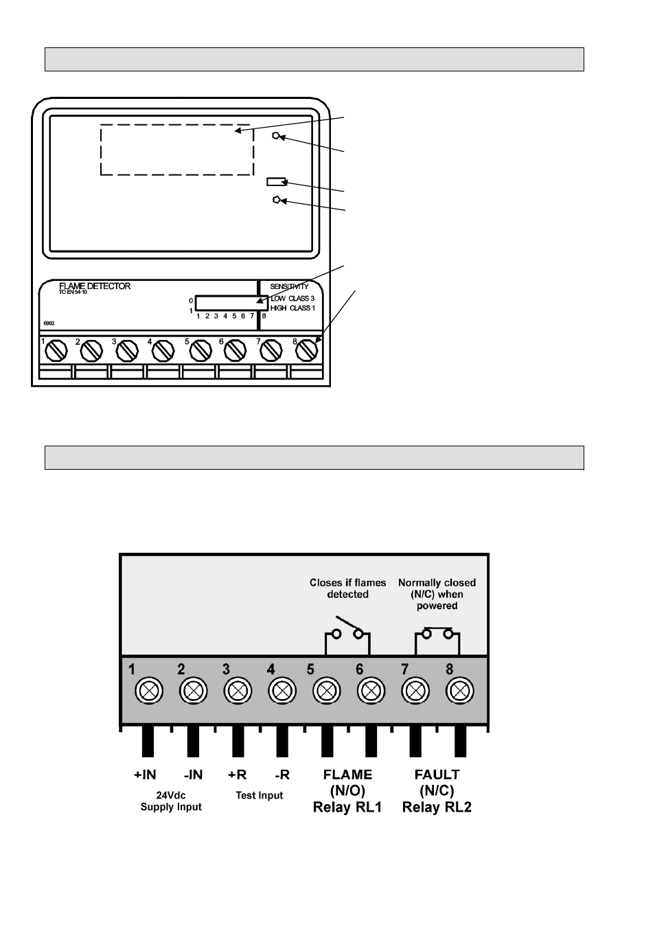
Detector Interior
IR Optics (IR optical flame sensors and filters)
Supply ON (Green) (steady if detector
functioning correctly)
Fire (Red) (indicates a FIRE detected)
Test (Yellow) (indicates detector in test mode)
DIL Switch (select detector functions)
Connection Terminals
Fig 4
Detector with Front Cover removed
Electrical Connections
The flame detector has eight connection terminals as show in Fig 5. Removing the front cover of the
flame detector accesses the connections. The cable is passed through the gland holes in the base of the
detector. Note – When the IFD-E is used on a Conventional system a Fire Resistor will be required
across the FLAME relay, the value of this resistor will be dependent on Control Panel, check with
manufacturer.
Fig 5
Electrical Connection Terminals (for Conventional system)