Hochiki IFD-E User Manual
Page 10
10
Hochiki Europe (UK) Ltd
2-3-0-808/ISS3/OCT11
Detector Supply Current
i @ 24Vdc
DIL Switch
Setting
Comment
Normal
Quiescent
Current
Alarm
(Fire) Current
1
2
3
4
3mA
9mA
0 0 0
0
Lowest power configuration,
RL1 only
4mA
20mA
0
0
1
0 For 4-20mA systems, no relays
8mA
14mA
1 1 0
0
Lowest power configuration &
relays
8mA
20mA
1
1
0
1 For 4-20mA systems & relays
8mA
28mA
1 1 1
1 Fire
control
panels
Table 4 Detector Supply & Alarm Currents
If the detector supply current falls below the normal quiescent current consumption then a fault is present.
This could be simply an open circuit cable fault or a fault within the detector possibly due to the detector
being taken over its rated temperature.
Detectors can be connected in parallel increasing the overall quiescent current required. The alarm
current signal will remain the same with the additional quiescent current drawn from other detectors.
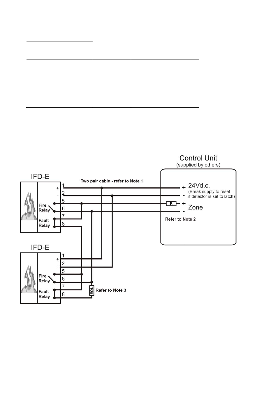
Fig 9
Basic 4 Wire Connection Diagram
NOTE 1
Screened cable should be used with one end of the screen connected to earth. Also care should be
taken not to run the detector cable next to power cables.
NOTE 2
R = To indicate fire to control unit or interface.
For example, 470R
NOTE 3
EOL = End of line device required by some
control units. This is required to monitor the
cable to the detectors and prevent fault
indications on the control unit.