Installation, Functional testing – Hochiki IFD-E User Manual
Page 15
Hochiki Europe (UK) Ltd
15
2-3-0-808/ISS3/OCT11
Installation
It is important that the detectors are installed in such a way that all terminals and connections are
protected to at least IP20 with the detector cover fitted. The earth bonding terminals are provided for
convenience where continuity of a cable sheath or similar if required.
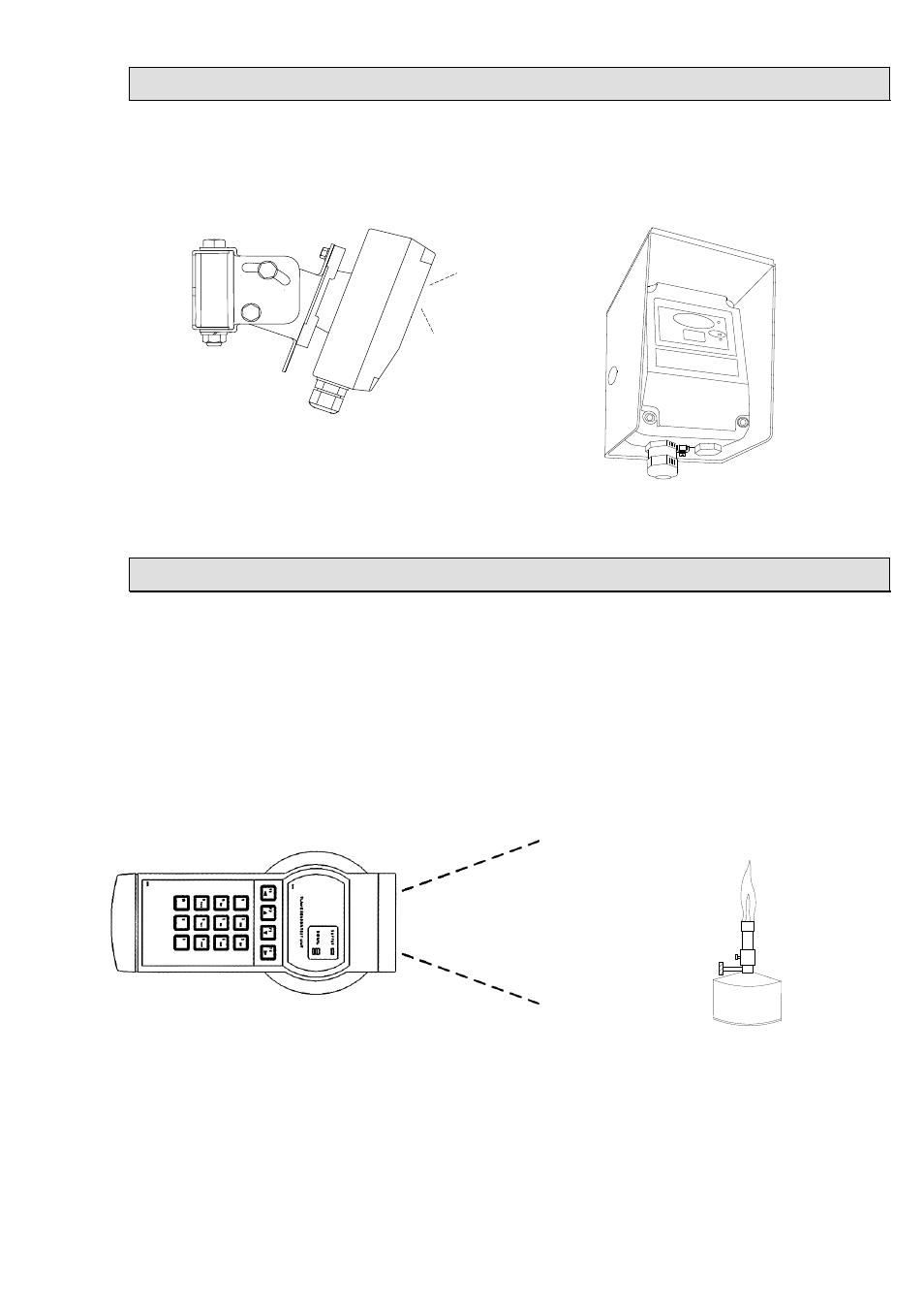
Adjustable mounting brackets and weather shields are available as shown below in Figs 14 and 15.
Fig 14
Stainless Steel Adjustable Mount
Fig 15
Stainless Steel Weather Shield
Functional Testing
When 24Vdc power is applied to the detector the green
supply on indicator LED will illuminate. The fault relay
RL2, if selected with the DIL switch, will energise and
the contact between terminals 7 and 8 will close.
If 24Vdc is applied to terminals 3 and 4 or terminal 3 is
linked to terminal 1 the detector will perform a self-test.
It does this by causing internal optical test sources to
simulate the behaviour of flames and the detector will
alarm.
Alternatively a portable flame sensor test
unit is available to generate simulated
flame behaviour and test the detector a
few metres in front of the detector. See
Fig 16.
Finally, provided it is safe to do so, carry
out a flame test using a flickering flame
source, such as a portable Bunsen
burner. See Fig 17.
A still non-flickering flame will not
produce a response from the detector
Fig 16
Portable Flame Detector Test Unit
Fig 17
Portable Bunsen Burner