Hochiki CHQ-DZM(SCI)-IS User Manual
Page 2
Hochiki Europe (UK) Limited
2-3-0-1366/ISS3/DEC11
Setting the Loop Address
The analogue address of the Module is set using the first 7
switches of the 8-bit DIL switch, which in the case of the
Standard CHQ is located through the cut-out section on the
top of the PCB cover. On the DIN version, this switch is
located on the edge of the PCB behind the clear door (see
Fig 3).
The switches are numbered 1 to 8 (left to right):
CHQ
MODULE
SWITCH UP ON
SWITCH DOWN OFF
DIN
MODULE
SWITCH UP OFF
SWITCH DOWN ON
The switches should be set using a small-tipped screwdriver
or similar.
Refer to the Address Chart (Fig 5) on page 3 for a quick
reference on addresses.
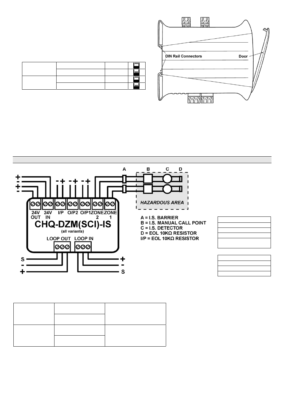
Fig 3
DIN Rail Mountable CHQ Module
Connection Details
The CHQ-DZM(SCI)-IS should be connected to the loop as shown below, the module does not support any line continuity
options, therefore, if manual Call Points are to be interfaced to the unit then these should be connected first. Detectors
should be connected to the CHQ-DZM(SCI)-IS in accordance with Hochiki’s I.S. certification.
NOTE: The CHQ-DZM(SCI)-IS must be installed in the safe area along with the barrier.
Fig 4
Compatible Barrier
Types
The CHQ-DZM(SCI)-IS
and CHQ-DZM/DIN(SCI)-
IS are capable of
supporting the barrier
types listed below.
Galvanic Isolators
MTL5561
KFD0-CS-Ex1.51P
KFD0-CS-Ex2.51P
MTL5061 & MTL4061
(older types)
Zener Barriers
MTL7728+
MTL7787+
MTL728+ (older type)
Setting EOL Monitoring Option
Select the required EOL monitoring option using the 2-bit DIL switch.
CHQ MODULE
SWITCH 1 DOWN
I.S. MODE*
SWITCH 2 UP
DIN MODULE
SWITCH 1 UP
I.S. MODE*
SWITCH 2 DOWN
* Fire alarm control panel compatibility required for these products.