Hochiki CHQ-DSC/M(SCI) User Manual
Chq modules installation instructions, Introduction, Components
Hochiki Europe (UK) Ltd
Page 1
2-3-0-1730/ISS3/DEC13
CHQ MODULES INSTALLATION INSTRUCTIONS
Products Covered: CHQ-DSC (Dual Sounder Controller), CHQ-DRC2 (Dual Relay Controller) &
CHQ-MRC2 (Mains Relay Controller)
Introduction
The CHQ "Smart-Fix" Range of Modules consists of the following models:
Mains Relay Controller
Dual Sounder Controller
Dual Relay Controller
CHQ-MRC2(SCI)
CHQ-MRC2/DIN(SCI)
CHQ-DSC(SCI)
CHQ-DSC/M(SCI)
CHQ-DSC/DIN(SCI)
CHQ-DRC2(SCI)
CHQ-DRC2/DIN(SCI)
Note: (SCI) indicates all modules feature an integral short-circuit isolator. DIN indicates Module housing is designed to fit
standard “Top Hat” DIN Rail.
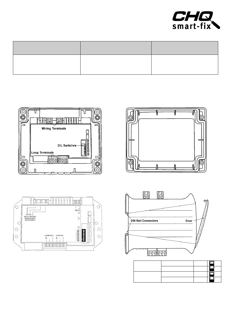
Components
Standard "Smart-Fix" Modules are supplied as two individual components (see Fig 1 & 2). DIN versions are supplied as
one unit (see Fig 4).
Fig 1
Fig 2
"Smart-Fix" CHQ Module (Back Plate inc PCB Component)
(Note: configuration of Wiring Terminal blocks differs between
models)
CHQ-LID Transparent Module Lid
(Supplied with four screws and acrylic retaining
washers)
Fig 3
Fig 4
Mains Relay Controller Adaptor Plate
DIN Rail Mountable CHQ
Setting the Loop Address
The analogue address of the Module is set using the first 7
switches of the 8-bit DIL switch, which in the case of the
Standard CHQ is located through the cut-out section on the top
of the PCB cover. On the DIN version, this switch is located on
the edge of the PCB behind the clear door (see Fig 4).
The switches are numbered 1 to 8 (left to right):
CHQ MODULE
SWITCH UP
ON
SWITCH DOWN
OFF
DIN MODULE
SWITCH UP
OFF
SWITCH DOWN
ON
The switches should be set using a small-tipped screwdriver or similar.
Refer to the Address Chart (Fig 7) on page 5 for a quick reference on addresses. (contd on page 4)