Safe area, Hazardous area, Connection details – Hochiki CHQ-ISM/DIN User Manual
Page 2: Fig 1, Fig 2
Hochiki Europe (UK) Limited
2-3-0-1469/ISS1/SEPT13
Connection Details
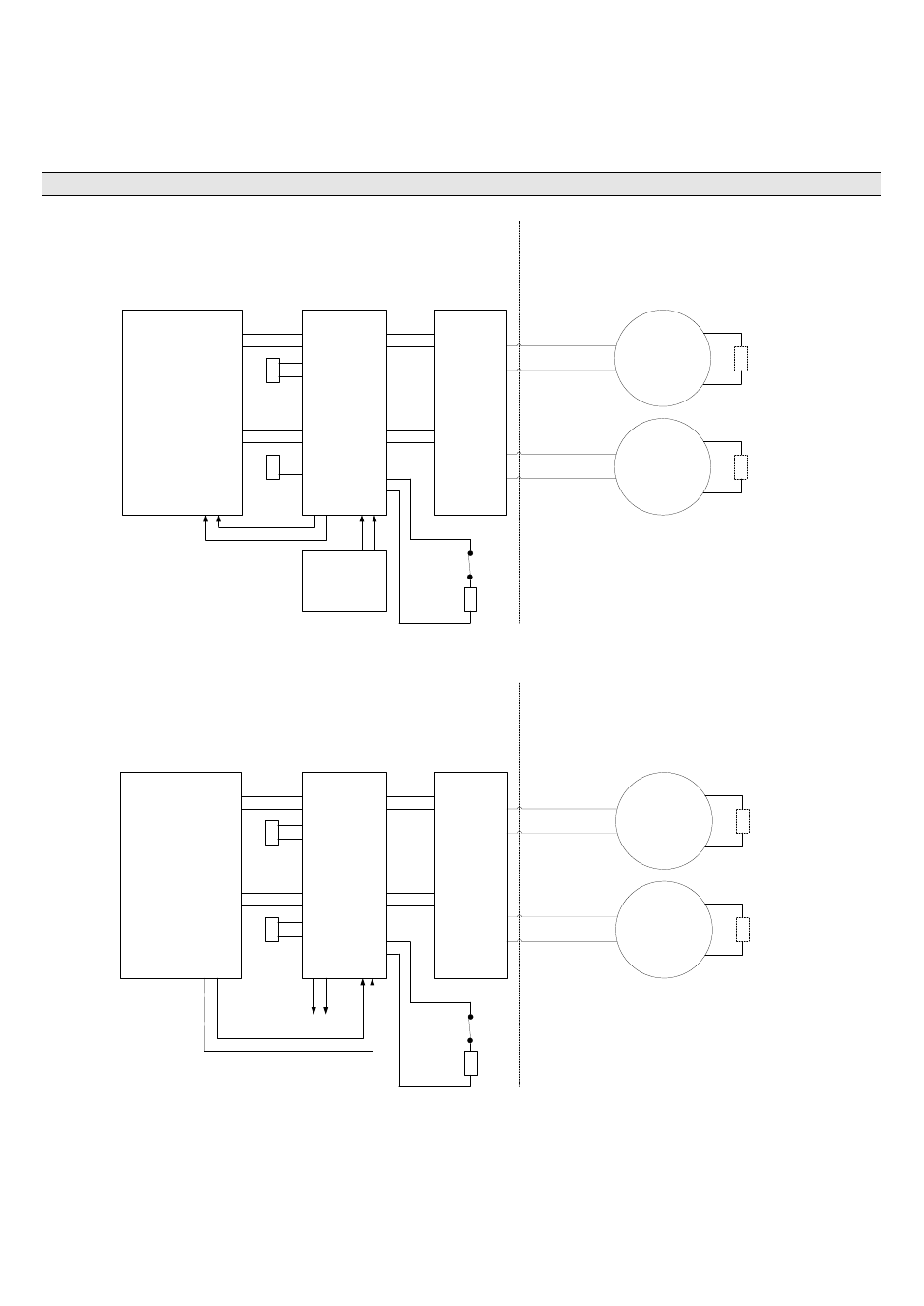
The CHQ-ISM should be connected as shown in Fig 1 or Fig 2 below, the I.S. device can be either a sounder
or beacon. See Table 3 which shows which I.S. devices have been tested for compatibility with the different
barrier types. Table 3 also shows whether an EOL device is required for compatibility; if required this should
always be placed at the furthest end of the cable, preferably in the terminals of the I.S. device.
NOTE: The CHQ-ISM should always be installed in the safe area along with the barrier.
SAFE AREA
EOL
CHQ-DSC or
Sounder Circuit
CH1
Barrier
24V
PSU
CHQ-ISM
+
-
HAZARDOUS AREA
SNDR
CCT1
SNDR
EOL1
SNDR
CCT2
SNDR
EOL2
EOL
+
-
+
-
+
-
CH2
+
-
IS
BARRIER 1
IS
BARRIER 2
24V IN
24V OUT
IS
device
IS
device
Refer to instructions to see if EOL is
required to be fitted.
*
*
*
24V IN
Input
EOL
EOL
EOL
Fig 1
SAFE AREA
EOL
Panel Sounder
Circuits
CH1
Barrier
To other
Equipment
CHQ-ISM
SNDR
CCT1
SNDR
EOL1
SNDR
CCT2
SNDR
EOL2
EOL
+
-
+
-
+
-
CH2
+
-
IS
BARRIER 1
IS
BARRIER 2
24V
OUT
24V IN
IS
device
IS
device
Refer to instructions to see if EOL is
required to be fitted.
*
*
*
24V
AUX
Input
EOL
Fig 2