Caution – Harrington Hoists and Cranes (N)ER Hoist - ((N)ER1) User Manual
Page 12
12
3.0 Preoperational Procedures
3.1
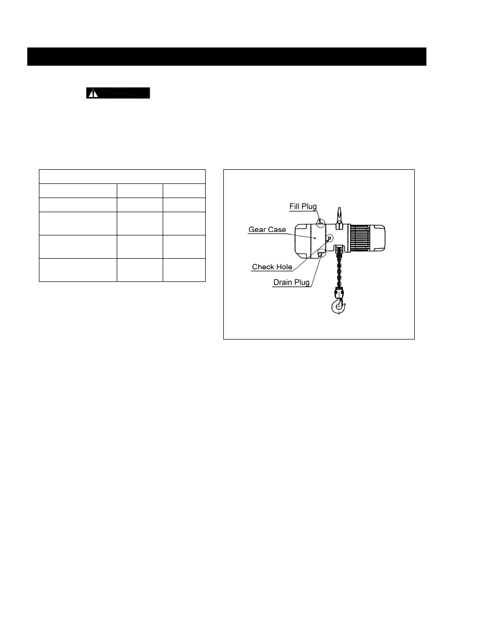
Fill Gear Box with Oil
3.1.1
CAUTION
The ER (with mechanical load brake/friction clutch) uses different gear oil than the
NER (with friction clutch).
DO NOT use any oil or quantity other than that listed below.
3.1.2
For a new hoist the correct quantity and type of oil is supplied with the hoist in separate container(s).
Remove the fill plug from the top of the hoist and connect the flexible pour tube to the oil container.
Pour in all of the oil from the separate container(s), then replace the fill plug.
3.1.3 Refer
to
Section 6.2
when replacing the gear oil or checking the gear oil level.
Table 3-1
Amount of Gear Oil
Figure 3-1
Oil Plug Locations
Capacity Code
quarts liters
001H, 003S, 005L
0.74
0.7
003H, 005S, 010L,
010M
1.06
1.0
010S, 015S, 020L,
020M, 030C
1.80
1.7
020S, 025S, 030L,
030S, 050L
3.17 3.0
NER Gear Oil:
Harrington standard: Bonnoc M260 (NIPPON OIL)
Acceptable equivalent: Meropa 320 (TEXACO)
Acceptable equivalent: Meropa 320 (CALTEX)
ER Gear Oil:
Harrington standard: Antoil super B (NIPPON OIL)
Acceptable equivalent: Meropa No.68 (TEXACO)
3.2 Chain
3.2.1
The quantity and location of the chain components including cushion rubbers, chain springs and striker
plates depend on the hoist model, capacity and limits switches. Never operate the hoist with incorrect,
missing or damaged chain components. Refer to the hoist's nameplate,
Table 3-2
, and
Figures 3-2, 3-
3, and 3-4
and ensure that all chain components are in the correct location and properly installed.
3.2.2
When the hoist is used without a chain container, the free end of the chain is attached to the hoist body
as shown in
Figure 3-4
. Connect the no load end of the chain to Chain Guide A with the End Wire or
End Suspender
provided. For 5 ton hoist, connect the no load end of the chain directly to Chain Guide
A if Chain Guide A is notched to accept the chain. Make sure the chain remains free of twists and the
chain Stopper is installed on the correct link. Refer to
Table 3-2
for proper placement of Stopper.