Harrington Hoists and Cranes (N)ER Load Limiter - ((N)ER1) User Manual
Page 10
9
1) Remove the split pin, slotted nut and chain pin that connect the Load Chain to the Connection Yoke.
2) Bolt the LL to the Connection Yoke, orienting the LL Case Cover toward the hoist motor.
3) Connect the Load Chain to the LL using the Chain Pin, Slotted Nut and Split Pin. Make sure that the
load chain is not twisted. Make sure that the Bottom Hook is not capsized (refer to Figure 3-7 in section
3-2 of the ER, NER and SNER Owner’s Manual)
4) Remove the Chain Stopper from the load Chain 8 links below the LL. This Stopper is not used when
the hoist is equipped with the LL. The other Chain Stopper, on the no-load end of the Load Chain, is
still needed. Do NOT remove the Chain Stopper from the no-load end of the Load Chain!
5) Pass the LL Cable over the hoist body on the control cover side of the suspension plate as shown in
Figure 3-1. Keep the electrical component mounting Plate free and control cover open for the
installation of the Socket Frame Holder L and to make the necessary electrical connections.
3.2 Socket Frame holder and Load Limit Relay
3.2.1
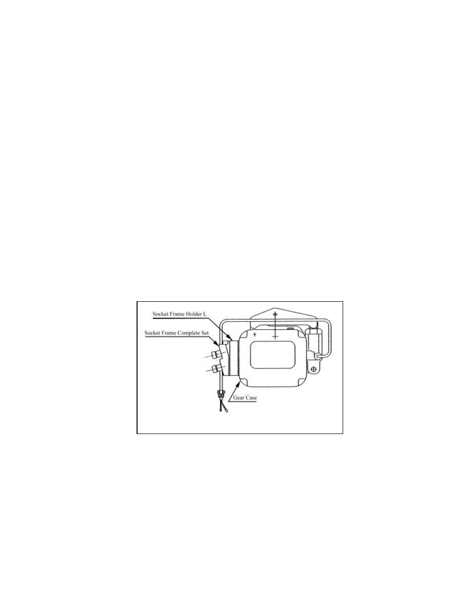
The Socket Frame Holder L mounts between the Socket Frame Complete Set and the Gear Case. Refer
to Figures 3-2 below and install as follows:
1) Remove the Socket Frame Complete Set and 4 & 5 Pin Socket Assemblies by:
a) Disconnecting the leads coming from the 4 Socket assemblies.
b) Remove the 4 mounting screws.
2) Install the Socket Frame Holder L and the Socket Frame Complete Set supplied with the Load Limiter
Kit. This Socket Frame Complete Set has longer leads required to make the electrical connections. Be
sure to place the packing/gaskets between the Gear Case and Socket Frame Holder L, and between
the Socket Frame Holder L and Socket Frame Complete Set.
3) Attach the LL cable to the Socket Frame Holder L. Refer to Figure 3-3.
Fig. 3-2