Mounting positions / lubrication – Grove Gear Helical-Worm Cast Iron (S Series) User Manual
Page 5
Phone: (262) 878-1221
Fax: (262) 878-1968
5
Mounting Positions / Lubrication
Motorized Reducers & Gearmotors
The Reducer and Motor are assembled at the factory, and
filled with the proper quantity of lubricant based on your
specified mounting position. Integral Gearmotors are
supplied with 3 phase 230/460v totally enclosed, fan cooled
(TEFC) 1750 rpm general purpose motors. Special integral
gearmotors are available. Consult the factory for details.
Standard Integral Gearmotors and Motorized Reducers are
assembled at the factory with the conduit box and the conduit
opening at the position illustrated in the dimensional section
of the catalog. The user may rotate the body of the motor to
reposition the conduit box (in 90° increments from the
original position). The conduit opening may also be
repositioned at 90° increments from the original position.
Both operations may be performed without disassembling
the drive.
Lubrication
Size 8472 through 8774 Reducers and Gearmotors are filled
with gear lubricant at the factory, to the correct level for the
mounting position specified on the order. This lubricant is
recommended for continuous operation with ambient
temperatures of 40° to 100°F (4° to 38° C) and operating
temperature to 225°F (107° C).
If the mounting position is changed, the oil
quantity must be adjusted to obtain the proper oil level per
the Lubrication Instruction enclosed with each unit. Mounting
position must be one shown on page 4. Consult the factory if
you are not certain of the correct oil level or quantity. Consult
the factory for mounting positions not shown.
For Double and Triple reduction units and the secondary
unit of quad reduction units, use Mobil 600W Cylinder oil,
or equivalent worm gear lubricant (ISO VG 460 AGMA 7
Comp.). For the primary unit of quad reduction units, use
Mobilgear 630 gear lubricant or equivalent (ISO VG 220
AGMA 5 EP).
Consult the factory for recommendations for other ambient
temperatures or intermittent duty.
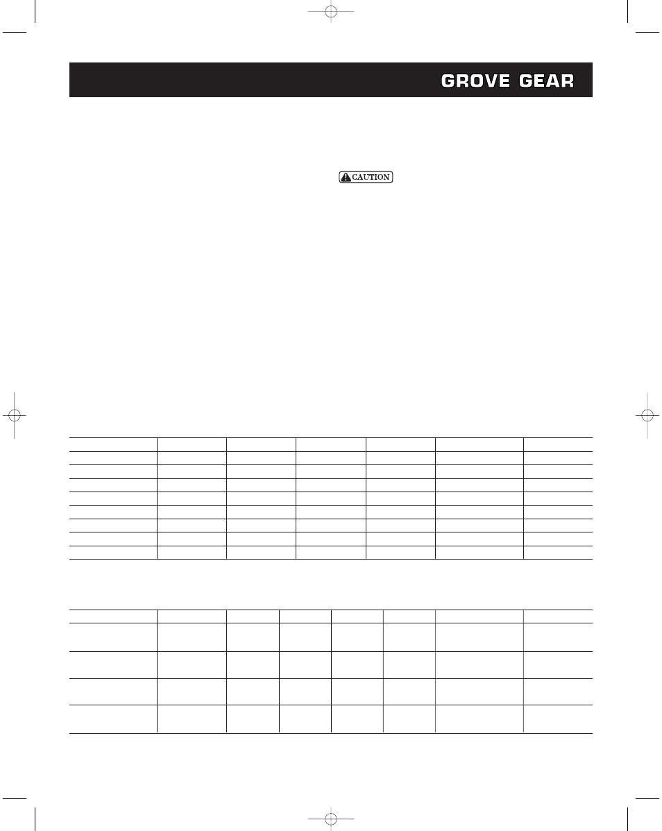
Approximate Oil Capacity (pints) Double and Triple Reduction
Mounting Position
Reducer Size
B3/B6
B8
V5/V5I
V6/V6I
B6/B8I
B3I/B6II
8472
1.7
2.4
1.9
1.9
Contact Factory
2.1
8473
2.1
2.8
2.2
2.2
Contact Factory
2.8
8572
2.0
3.9
3.3
3.3
Contact Factory
3.7
8573
2.8
4.5
3.9
3.9
Contact Factory
4.8
8672
4.3
5.6
5.1
5.3
Contact Factory
6.0
8673
6.3
8.3
7.3
7.3
Contact Factory
8.0
8772
7.7
14.0
11.6
11.6
Contact Factory
12.7
8773
11.2
18.0
15.1
15.1
Contact Factory
16.2
Approximate Oil Capacity (pints) Quadruple Reduction
(1)
Mounting Position
Reducer Size
Unit
B3/B6
B8
V5/V5I
V6/V6I
B6/B8I
B3I/B6II
8674 Primary
1.9
2.2
1.6
1.6
Contact
Factory
2.5
Solid Input Shaft
Secondary
4.3
5.6
5.3
5.3
Contact Factory
6.0
8674
Primary
1.6
3.0
2.3
2.3
Contact Factory
2.3
“C” Face Input
Secondary
3.6
9.0
8.3
8.6
Contact Factory
10.8
8774
Primary
3.0
3.1
2.4
2.4
Contact Factory
3.6
Solid Input Shaft
Secondary
7.7
14.0
11.6
11.6
Contact Factory
12.7
8774
Primary
1.6
3.0
2.3
2.3
Contact Factory
2.3
“C” Face Input
Secondary
7.7
14.0
11.6
11.6
Contact Factory
12.7
(1) Quad reduction units are compound units, the primary and secondary units are filled separately. Refer to the model table above and use the oil
capacities shown.
HelicalWormMan,7-07 8/2/07 11:46 AM Page 5