Grant Part #61046 - Revolution User Manual
Page 2
DISABLING AND REMOVAL OF THE AIRBAG MODULE
1. Position the steering wheel so that it is pointed straight ahead. Write down all of your radio presets
as these may be lost when you disconnect the battery cable.
2.
NOTICE
- Disconnect the negative battery cable and wait at least
1 full minute
for the circuit to
completely discharge before proceeding.
CAUTION:
Failure to fully deplete the backup power
supply could result in an accidental deployment and possible injury.
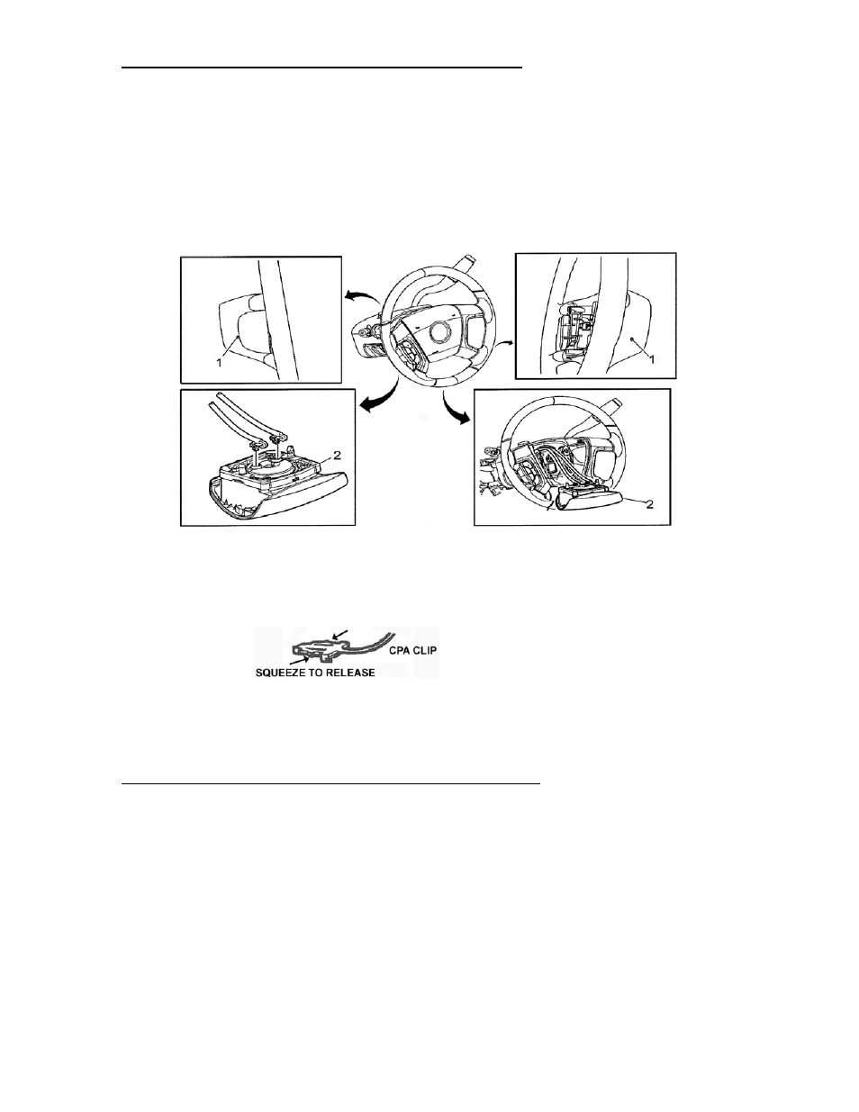
3. Using a 3-4mm (1/8”-5/32”) Allen wrench release the 2 spring fasteners by pushing inward through
the access holes. The access holes are located on both sides of the rear plastic steering wheel
shroud. See number 1 in the illustration below.
4. Lift and partially remove the airbag module from the steering wheel in order to expose the electrical
connectors on the back side. Take care not to pull on any of the wiring. See number 2 in illustration.
5. The airbag electrical connections have a safety locking connector-position assurance (CPA) clip that
must be disconnected before you can remove the electrical connectors from the module.
6. Disconnect the electrical connectors from the airbag module.
7. Remove the airbag module from the steering wheel and place the module face up on the floor, seat
or work bench. If you carry the module make sure the trim cover is pointed AWAY from your body.
REMOVING THE STEERING WHEEL FROM THE VEHICLE
1. Disconnect the wheel switch wiring harness at the column connector. Do not pull excessively on
the connector or clockspring mechanism and do not turn the clockspring now or at any time
during the remainder of the installation.
2. Loosen the steering wheel retainer nut until 2 or 3 threads are left engaged. Wiggle (rock) the
steering wheel back and forth while pulling upward until it disengages from the shaft, and then
remove the retainer nut and wheel from the vehicle.
3. Unplug the connector from the right side of the zinc plated horn mechanism (this connector usually
has a pinkish colored insulator. Loosen the 4 #T-30 Torx screws holding this horn mechanism to the
wheel. When the screws are loose lift this entire mechanism out of the wheel.
4. Remove the 4 small #T-15 Torx screws holding the copper horn contacts to the plastic trim and then
separate the contacts from the trim piece.