Sst-st60f-esb – SilverStone ST60F-ESB User Manual
Page 4
03
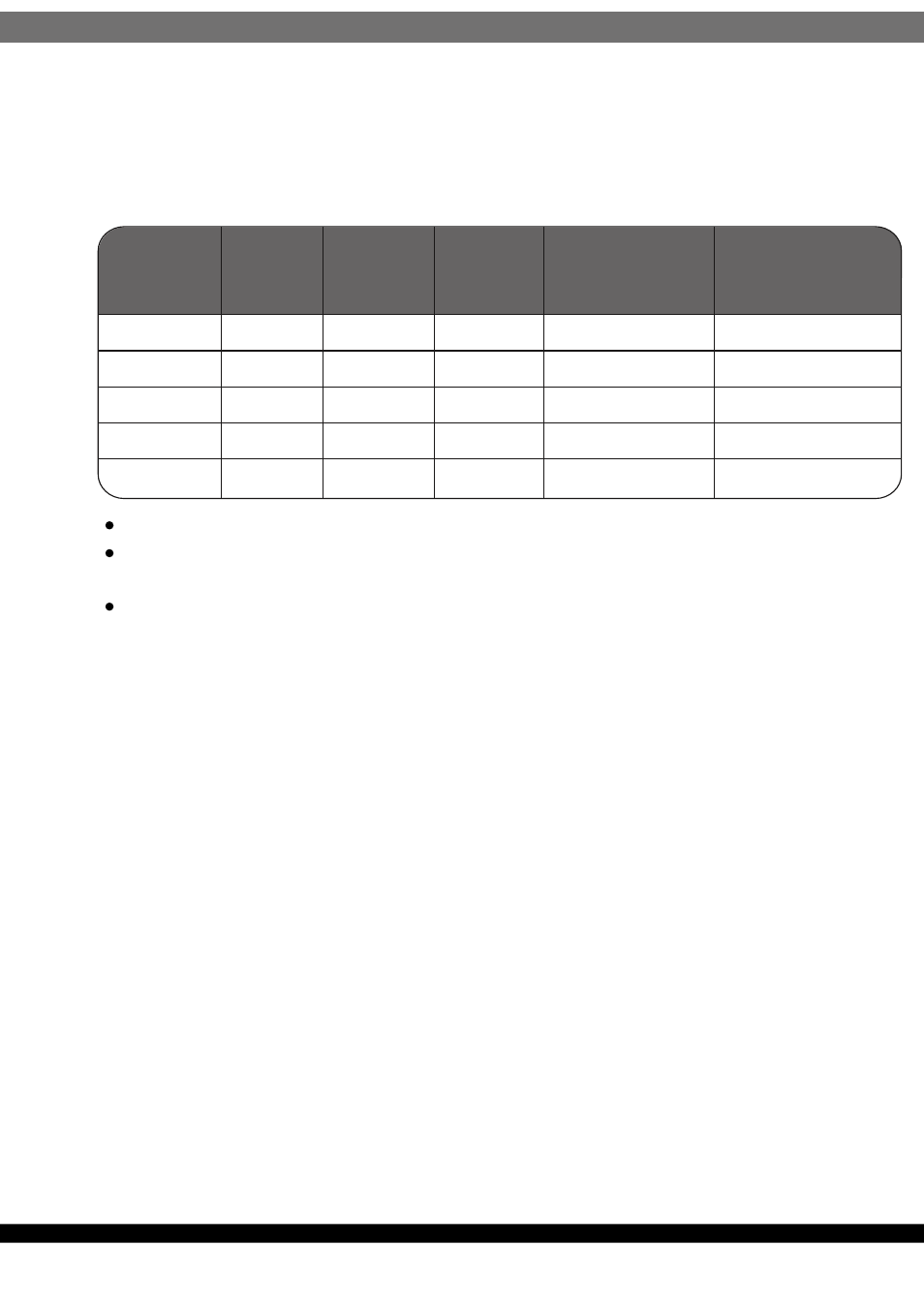
SST-ST60F-ESB:
Output
Voltage
Load
MIN
Range
MAX
Peak
Regulation
Ripple & Noise
P-P Max.
1. +5V
2. +3.3V
3. +12V
4. -12V
5. +5Vs
0.2A
0.1A
0.6A
0.0A
0.0A
22.0A
22.0A
45.0A
0.3A
2.5A
3.5A
±5%
±5%
±5%
±10%
±5%
50mV
50mV
120mV
120mV
50mV
Maximum continuous total DC output power should not exceed 600W.
Maximum continuous combined load on +3.3VDC and +5VDC outputs shall
not exceed 120W.
Maximum combined load on 12V outputs shall not exceed 540W.
NOTE:
Noise test should be measured with 20 MHz bandwidth frequency oscilloscope.
The output terminal shall add a tantalum capacitor of 10uF in parallel with
a ceramic capacitor of 0.1uF.
NOTE:
Noise test should be measured with 20 MHz bandwidth frequency oscilloscope.
The output terminal shall add a tantalum capacitor of 10uF in parallel with
a ceramic capacitor of 0.1uF.
3.2 Remote On/Off Controlled mode
TTL level
"H" 2.0 V – 5.25 V
"L" 0.0 V – 1.0 V
The PSON# signal is required to remotely turn on/off the power supply, PSON#
is an active low signal that turns on the output power rails. When this is not pulled
low by the system, or left open, the outputs (except the +5VSB) turn off.
This signal is pulled to a standby voltage by a pull-up resistor internal to the
power supply.
3.3 Regulation
The cross regulation defined as follows, the output regulation should be within
the specified range.