St30gf-mauual-v1-p7-p8 – SilverStone ST30GF Manual User Manual
Page 5
ST30GF
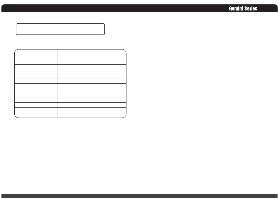
5.2 Humidity
6. Agency Requirements
6.1 Safety Certification.
Table 8 –Safety Certification
6.2 AC Input Leakage Current
Input leakage current from line to ground will be less than 3.5mA rms. Measurement will be
made at 240 Vac and 60Hz.
7. Redundant Power Supply Function
7.1 Redundancy
The redundant power supply is N+1=N (300W+300W=300W) function power supply, each one
module is redundancy when any one module was failed. To be redundant each item must be in
the hot swap power supply module.
07
Operating Humidity Range:
Non-Operating Humidity Range:
20% ~ 90%RH non-condensing
5% ~ 95%RH non-condensing
Product Safety:
RFI Emission:
PFC Harmonic:
Flicker:
Immunity against:
-Electrostatic discharge:
-Radiated field strength:
-Fast transients:
-Surge voltage:
-RF Conducted
-Voltage Dips and Interruptions
UL 60950-1 2000Edition, IEC60950-1, 3rd Edition
EU Low Voltage Directive (73/23/EEC) (CB)
TÜV
FCC Part15 ( Radiated & Conducted Emissions )
CISPR 22,3rd Edition / EN55022: 1998 + A1: 2000)
EN61000-3-2:2000
EN61000-3-3: 1995 + A1: 2002
EN55024: 1998 + A1: 2001 and A2: 2003
-IEC 61000-4-2
-IEC 61000-4-3
-IEC 61000-4-4
-IEC 61000-4-5
-IEC 61000-4-6
-IEC 61000-4-11
08
7.2 Hot Swap Requirements
The redundant power supply modules shall be hot swappable. Hot swapping a power supply
is the process of inserting and extracting a power supply from an operating. During this
process the output voltage shall remain within the limits specified in Table 7 with the
capacitive load specified Table 9. The Sub-system shall not exceed the maximum inrush
current as specified in section 2.2. The power supply can be hot swapped by the following
methods:
AC connects with each module. Up to two power supplies may be on a single AC power
source. Extraction: The AC power will be disconnected from the power supply first and then
the power supply is extracted from the sub-system. This could occur in standby mode or
powered on mode. Insertion: The module is inserted into the cage and then AC power will be
connected to the power supply module.
For power modules with AC docking at the same time as DC. Extraction: The module is
extracted from the cage and both AC and DC disconnect at the same Time. This could occur
in standby or power on mode. No damage or arcing shall occur to the DC or AC contacts
which could cause damage. Insertion: The AC and DC connect at the same time as the
module is inserted into the cage. No damage to the connector contacts shall occur. The
module may power on or come up into standby mode.
Many variations of the above are possible. Supplies need to be compatible with these
different variations depending upon the sub-system construction. In general, a failed (off by
internal latch or external control) supply may be removed, then replaced with a good power
supply (must use the same model); however, hot swap needs to work with operational as well
as failed power supplies. The newly inserted power supply may get turned on by inserting the
supply into the system or by system management recognizing an inserted supply and
explicitly turning it on.
7.3 LED Indicators
There shell is a single bi-color LED. The GREEN LED shall turn ON to indicate that all the
power outputs are available. The Orange LED shall turn ON to indicate that the power supply
has stand-by or failed shutdown due to over current, the Red LED shall turn ON to indicate
the Fan of the power supply has failed.
The LED(s) shall be visible on the power supply’s exterior face. The LED location shall
meet ESD requirements. LED shall be securely mounted in such a way that incidental
pressure on the LED shall not cause it to become displaced.