St30gf-mauual-v1-p3-p4 – SilverStone ST30GF Manual User Manual
Page 3
ST30GF
Ripple and Noise shall be measured using the following methods:
a) Measurements made differentially to eliminate common-mode noise.
b) Ground lead length of oscilloscope probe shall be 0.25 inch.
c) Measurements made where the cable connectors attach to the load.
d) Outputs bypassed at the point of measurement with a parallel combination of 10uF tantalum
capacitor in parallel with a 0.1uF ceramic capacitors.
e) Oscilloscope bandwidth of 0 Hz to 20MHz.
f) Measurements measured at locations where remote sense wires are connected.
g) Regulation tolerance shall include temperature change, warm up drift and dynamic load.
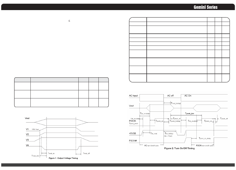
3.3 Timing Requirements
These are the timing requirements for the power assembly operation. The output voltages must rise
from 10% to within regulation limits (Tvout_rise) within 5 to 70mS. The +5V, +3.3V and +12V
output voltages should start to rise at about the same time. All outputs must rise monotonically. The
+5V output must occur first than the +3.3V output during any point of the voltage rise. The +5V
output must never be greater than the +3.3V output by more than 2.25V. Each output voltage shall
reach regulation within 50 ms (Tvout_on) of each other during turn on of the power supply. Each
output voltage shall fall out of regulation within 400 mS (Tvout_off) of each other during turn off.
Figure 1 and figure 2 shows the turn on and turn off timing requirement. In Figure 2, the timing is
shown with both AC and PSON# controlling the on/off of the power supply.
Table 4 – Output Voltage Timing
03
Item
Tvout_rise
Tvout_on
Tvout_off
Description
Output voltage rise time from each
main output.(+5Vsb < 70mS)
All main output must be within regulation
of each other within this time.
All main output must leave regulation
within this time
MIN
5
N/A
N/A
MAX
70
50
400
Units
mS
mS
mS
04
Table 5 – Turn On/Off Timing
Item
Tsb_on-delay
Tac_on-delay
Tvout_holdup
Tpwok_holdup
Tpson_on_delay
Tpson_pwok
Tpwok_on
Tpwok_off
Tpwok_low
Tsb_vout
Description
Delay from AC being applied to +5VSB is being within regulation.
Delay from AC being applied to all output voltages being
Within regulation.
All main output voltage stay within regulation after loss of AC
Delay from loss of AC deassertion of PWOK.
Delay from PSON# active to output voltage within regulation limits.
Delay from PSON# deactive to PWOK being deasserted.
Delay from output voltage within regulation limits to PWOK asserted
at turn on.
Delay from PWOK deasserted to output voltages (+5V, +3.3V, +12V)
dropping out of regulation limits.
Duration of PWOK being in the deasserted state during an off/on cycle
using AC or the PSON# signal. .
Delay from +5VSB being in regulation to O/Ps being in regulation at
AC turn on.
MIN
N/A
N/A
18
17
5
N/A
100
1
100
50
MAX
1500
2500
N/A
N/A
400
50
500
N/A
N/A
1000
Units
mS
mS
mS
mS
mS
mS
mS
mS
mS
mS