St30gf-mauual-v1-p5-p6 – SilverStone ST30GF Manual User Manual
Page 4
ST30GF
05
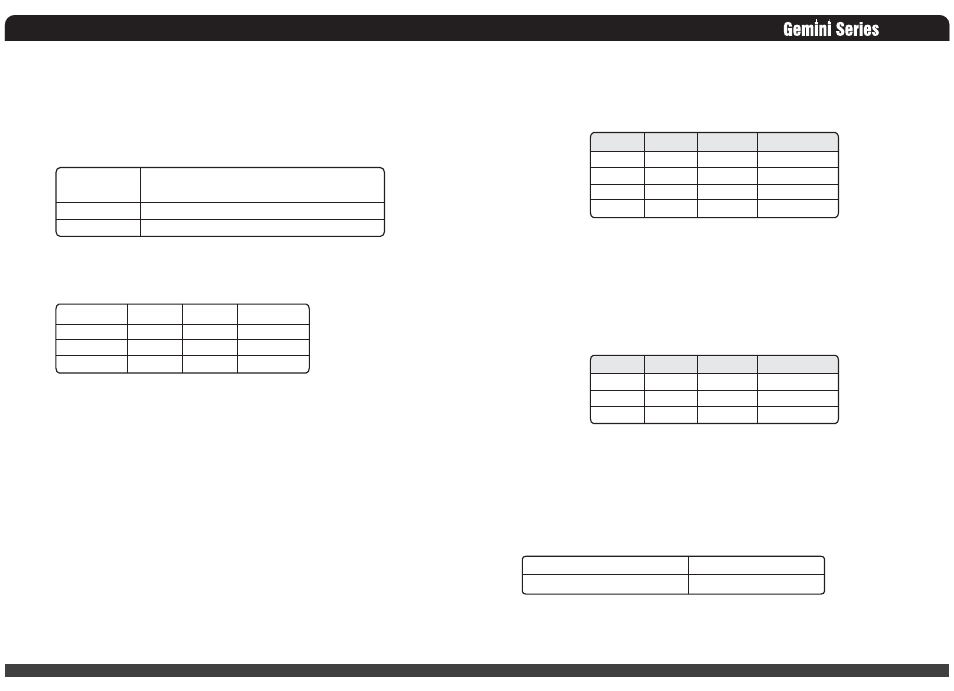
3.4 Remote On/Off Control: PSON#
The PSON# signal is required to remotely turn on/off the power supply. PSON# is an active
low signal that turns on the +5V, +3.3V, +12V,-5V and –12V power rails. When this signal
is not pulled low by the system, or left open, the outputs (except the +5VSB and V bias) turn
off. This signal is pulled to a standby voltage by a pull-up resistor internal to the power
supply.
3.5 Efficiency
The efficiency should be measured at 230VAC and with external fan power source at
specified loading. Test efficiency for a module.
Reference www.80plus.org all test conditions.
3.6 +5VSB (Standby)
The +5VSB output is always on (+5V Standby) when AC power is applied and power
switch is turned on. The +5VSB line is capable of delivering at a maximum of 2A for PC
board circuit to operate.
4. Protection
Protection circuits inside the power supply shall cause only the power supply’s main outputs
to shutdown. If the power supply latches off due to a protection circuit tripping, either an
AC cycle OFF for 15 sec or PSON #cycle HIGH for 1 sec must be able to restart the power
supply.
4.1 Over Power Protection
The OPP function shall work at 110%~160% of rating of output power, then all outputs shut
down in a latch off mode. The latch shall be cleared by toggling the PSON# signal or by
cycling the AC power. The power supply shall not be damaged from repeated power cycling
in this condition. If only one module works inside the power supply, the OPP is at
110%~160% of rating of power supply.
Signal Type
PSON# = Low
PSON# = High
Accepts an open collector/drain input from the system.
Pull-up to VSB located in power supply.
Power ON
Power OFF
20% Load
50% Load
100% Load
+12V
4.81A
12.03A
24.01A
+5VSB
0.4A
1A
2A
Efficiency
81%
85%
81%
4.2 Over Voltage Protection
Each hot swap module has respective OVP circuit. Once any power supply module shut down
in a latch off mode while the output voltage exceeds the over voltage limit shown in Table 7,
the other modules should deliver the sufficient power to the device continually.
Table 7 –Over Voltage protection
4.3 Over Current Protection
The power supply should contain the OCP function on each hot swap module. The power
supply should be shut down in a latch off mode while the respective output current exceeds the
limit as shown in Table 8. When the latch has been cleared by toggling the PSON# single or
cycling the AC input power. The power supply module should not be damaged in this
condition.
Table 8 –Over Current protection
4.4 Short Circuit Protection
The power supply shall shut down in a latch off mode when the output voltage is short circuit.
5. Environmental Requirements
5.1 Temperature
06
Voltage
+5V
+3.3V
+12V
5VSB
Minimum
+5.7V
+3.9V
+13.3V
+5.7V
Maximum
+6.5V
+4.5V
+14.5V
+6.5V
Shutdown Mode
Latch Off
Latch Off
Latch Off
Auto recovery
Voltage
+5V
+3.3V
+12V
Minimum
110%
110%
110%
Maximum
160%
160%
160%
Shutdown Mode
Latch Off
Latch Off
Latch Off
Operating Temperature Range:
Non-Operating Temperature Range:
0°C ~ 40°C (32°F~ 104°F)
-40°C ~ 70°C (-40°F~ 158°F)