Robinair Model 15448 User Manual
Page 2
Pump Components
Refer to graphic on next page.
1. Intake Fitting (upper fitting is
1
/
2
" Acme;
side fitting is
1
/
4
" MFL)
2. Gas Ballast Valve
(located beside handle base)
3. Oil Fill Port
4. Sight Glass
5. Die-Cast Aluminum Housing
6. Oil Drain
7. Molded Polycarbonate Base
8. Iso-Valve
TM
— isolates pump from system
9. High Torque Motor
10. Power Switch
11. Through-the-Handle Exhaust
12. Sure-Grip Handle
Table of contents
Warnings .............................................................2
Pump components................................................2
Robinair high performance vacuum pumps ..........3
Before using your vacuum pump ..........................4
To use the gas ballast feature...............................5
To shut down your pump after use .......................5
To maintain your high vacuum pump ....................5
Vacuum pump oil .............................................5
Oil change procedure ......................................5
Cleaning your pump.........................................5
Troubleshooting guide ..........................................6
Failure to start.......................................................6
Oil leakage .......................................................6
Failure to pull a good vacuum..........................6
Robinair pump specifications................................6
Replacement parts ...............................................7
Warranty coverage ...............................................7
Out of warranty ................................................7
Operating Manual
Warnings
2
For use on A/C-R systems
using CFCs, HCFCs, and HFCs
in conjunction with mineral oil,
ester oil, alkylbenzene oil, and
PAG oil as lubricants. Not for
use with ammonia or lithium
bromide systems. Not for use
with flammable refrigerants.
Wear safety goggles when working with
refrigerants. Refrigerants can cause
eye injury.
Incorrect use or connections may cause
electrical shock hazards. Read and
follow the instructions carefully and take
precautions to avoid electrical shock
hazards. All associated devices must
be grounded before energizing circuits.
Normal operating temperature will
cause certain external portions of
the pump to be hot to the touch. Do
not touch the pump housing or motor
during operation.
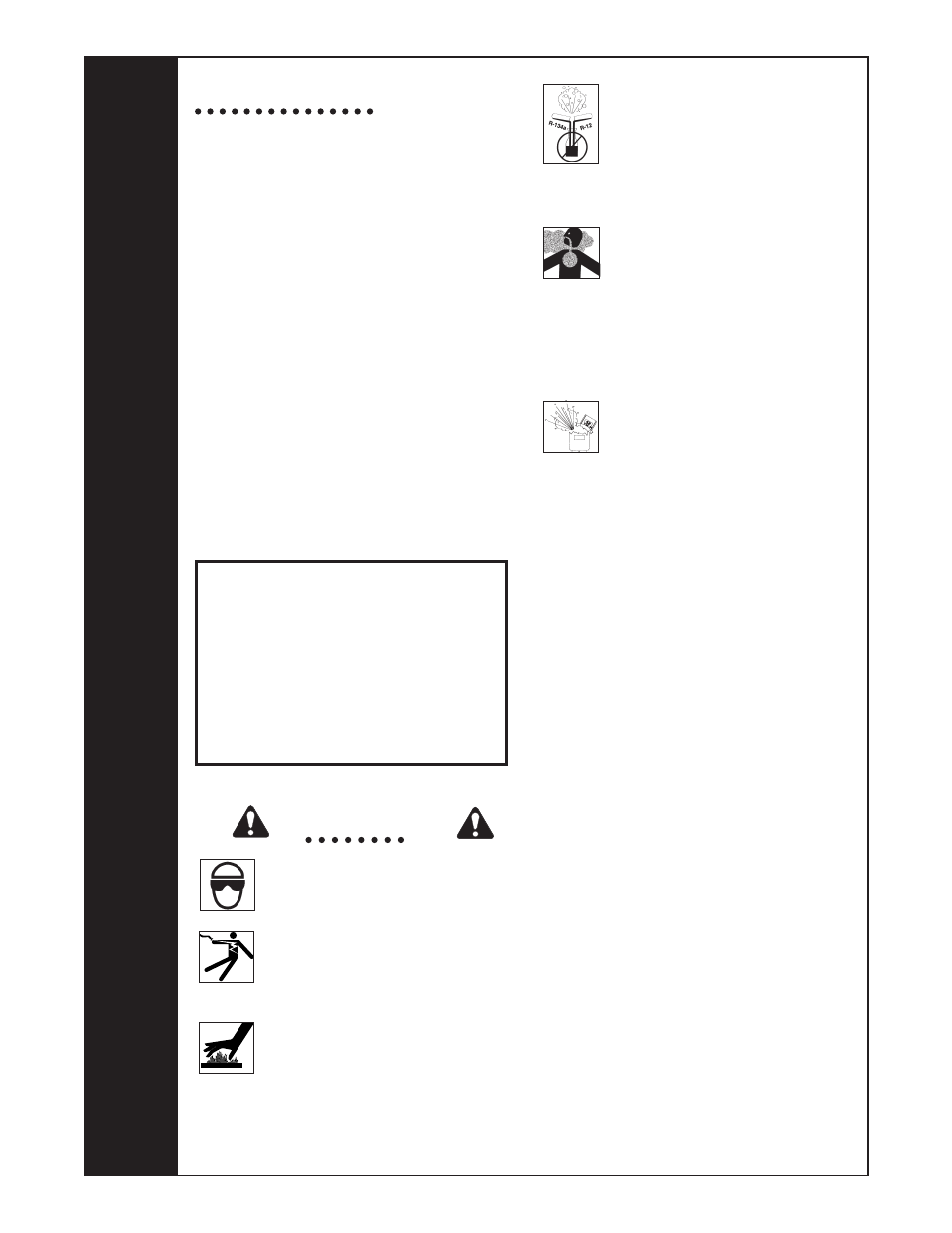
Use separate manifolds and
hoses for R-134a systems. Cross-
contamination with other refrigerant
types will cause severe damage to
the A/C system and to service tools
and equipment. Do not mix refrigerant
types through a system or in the
same container!
Avoid breathing refrigerant and
lubricant vapor or mist. Exposure may
irritate eyes, nose, and throat.
To remove R-134a from the A/C
system, use service equipment
certified to meet the requirements
of SAE J2210 (R-134a recycling
equipment). If accidental system
discharge occurs, ventilate work area
before resuming service.
HFC-134a service equipment or
vehicle A/C systems should not be
pressure tested or leak tested with
compressed air. Some mixtures of air/
HFC-134a have been shown to be
combustible at elevated pressures.
These mixtures are potentially
dangerous and may result in fire or
explosion causing injury or property
damage.
Additional health and safety
information may be obtained
from refrigerant and lubricant
manufacturers.