Reversomatic 4000 250ES2 User Manual
Page 3
790 Rowntree Dairy Road, Woodbridge ON, Canada L4L 5V3
Tel: 905-851-6701 Fax: 905-851-8376 [email protected]
w w w . r e v e r s o m a t i c . c o m
.. 3 ..
HOOD INSTALLATION (BE SURE POWER SUPPLY IS OFF BEFORE STARTING INSTALLATION)
1. Attach the damper (optional) section as shown on the previous page to the hood, align with ductwork in cabinet or wall.
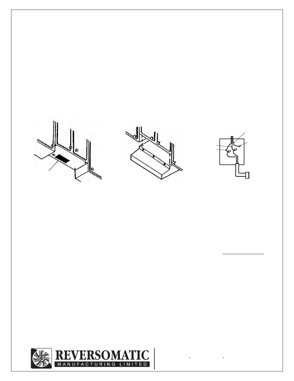
2. Guide the electrical cable into the knockout opening and hang the hood on screws previously installed. Tighten screws
securely (see Fig. 2)
3. When installing duct work make sure that damper
normally closes and opens freely, when blower is ON.
4. Run proper wiring to the hood location i.e. 120V / 60Hz AC Power source, with ground.
5. Connect the power supply to the hood leads, White to White, Black to Red and the ground wire to the green grounding
screw. Wiring must confirm to local and national electrical codes and must be done by a qualified person. (See Fig.3)
CLEANING INSTRUCTIONS
(DISCONNECT THE HOOD FROM POWER SUPPLY BEFORE CLEANING OR SERVICING)
1. Clean your range hood with a mild detergent or mild soap, NEVER USE HARSH ALKALIS OR ABRASIVES.
2. Completely dry the range hood with soft dry cloth before restoring power. NEVER IMMERSE ELECTRICAL PARTS IN
WATER.
3. Aluminum mesh grease filter may be washed using mild soap or detergent. However, heavy grease buildup may require
replacement with a new REVERSOMATIC grease filter.
(optional)
2. We recommend that after installation the bottom of the hood should be no less than 20” and no more than 30” above the
stove’s heating elements or burners.
3. Holding the hood in place, mark location of mounting screws in narrow end of keyhole slot in each corner of the hood.
4. Start the 4 mounting screws included with hood, but let them project so later the hood may be hung on them using the
keyhole mounting holes. (See Fig.1)
5. Mark the bottom of the cabinet if the top electrical knockout on the hood will be used or the wall if using rear electrical
knockout. Refer to the dimensions in the drawing for proper hole location. (Remove the appropriate electrical knockout
from the hood by using a screwdriver)
6. Using a 1 1/4” drill bit, drill the opening for the electrical connection (see Fig.1). If drilling in the wall, extra care should be
taken so existing electrical cables are not cut, creating a hazard.
7. Making the cabinet or wall for the duct opening selected following the dimensions in the drawing.
8. Using a saber saw or keyhole saw, cut the duct opening. If cutting in the wall, extra precaution should be taken so
existing electrical cables are not cut, creating a hazard.
Fig. 1
Preparation for
top outlet
Fig. 2
Fig. 3
FROM
HOOD
GREEN
GROUND
SCREW
GROUND
BLACK
WHITE
120 VAC POWER
WIRING W/ GROUND