Caution, Installation instructions – Reversomatic 4000 250ES2 User Manual
Page 2
CAUTION
1. For general ventilation use only. Do not use to exhaust hazardous or explosive materials and vapor.
2. To avoid damage to motor and impeller, keep construction material such as dry wall spray, construction dust, construction
debris, etc. off from the power unit and ducts leading to the unit.
INSTALLATION INSTRUCTIONS
GENERAL PREPARATION
1. To install this unit, you may require following tools and materials:
- Drill
- 1 1/4” wood bit for drilling electrical wiring access hole
- Philips head screwdriver
- Saber saw or keyhole saw for cutting the wall or cabinet openings
- Electrical tape
- Pencil, ruler, measuring tape and level for marking range hood location
2. Unpack the unit from the box and lay the unit upside down on a table. Use cardboard or paper to prevent scratching the
unit or table.
3. Remove the aluminum-mesh grease filter and install a fluorescent 4 pin 18 / 26 watt light bulb ( such as Panasonic
FDS18E35/4 or FDS26E35/4 or equivalent - BULB IS NOT SUPPLIED). Reinstall the filter.
790 Rowntree Dairy Road, Woodbridge ON, Canada L4L 5V3
Tel: 905-851-6701 Fax: 905-851-8376 [email protected]
w w w . r e v e r s o m a t i c . c o m
.. 2 ..
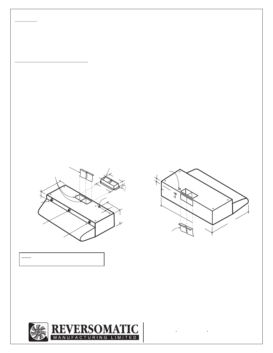
NOTE: To get maximum exhaust, turn ON both fans.
To prevent backdraft use outlet transition c/w
damper.
- 1/8” drill bit for drilling pilot holes
- Pliers / Tin snips
- Duct tape
- Electrical connector
PREPARING THE CABINET OR WALL FOR INSTALLATION
1. If the hood will be installed under cabinets that have a recessed bottom, then it will be necessary to attach wood mounting
strips (Not Included) to the bottom of the cabinet in the location where the unit will mount. The thickness of the strips
should be the same as the recess of the cabinet and they should be approximately 2” wide. Install the wood strips using
appropriate length of wood screws
(Not Included). Make sure the wood strips line up with the 4 keyholes of the hood.
Fan Speed
Control
ON / OFF
Switch
Light
Fan Speed
Control
Baffles
(Must be installed in
exhaust only)
Exhaust openings
Electrical Knockout
Optional
Outlet Transition c/w damper
(Recommended)
12"
1.5"
10"
2 1/16"
0.5"
3
3/16
"
10.5"
c/c
1.75"
6"
7.75"
Baffles for
vertical
installation
1.75"
30", 36"
19"
7.75"
Electrical
knockout