9060 high voltage controller - installation, I/o signal locations – Ransburg 9060 HV Controller 80100-XXX User Manual
Page 31
9060 High Voltage Controller - Installation
CP-13-05.3
26
The Relay Contact Outputs are normally
included as output signal indicators for a control
system and are wired using a few of the con-
ductors in the I/O cable. For more information
about the Relay Contact Outputs wiring, please
refer to the prior “Installation” section on that
topic.
A complete description of all of the signals
available in remote mode is provided in the
“Introduction” section of this service manual.
For more information on the behavior or timing
requirements for any of the signals, please refer
to the “Operations” section of this service
manual.
ALWAYS double check that the Con-
troller is unplugged from its AC outlet
before working with any internal wiring.
!
W A R N I N G
3. Route the selected shielded cable through
the standard I/O connector and secure it to
the connector as described in “I/O Connec-
tions” in the “Installation” section of this
manual so that the shield of the cable is
connected to the chassis of the enclosure.
Ensure that enough wire length is available
to allow for proper wiring of all of the I/O
signals.
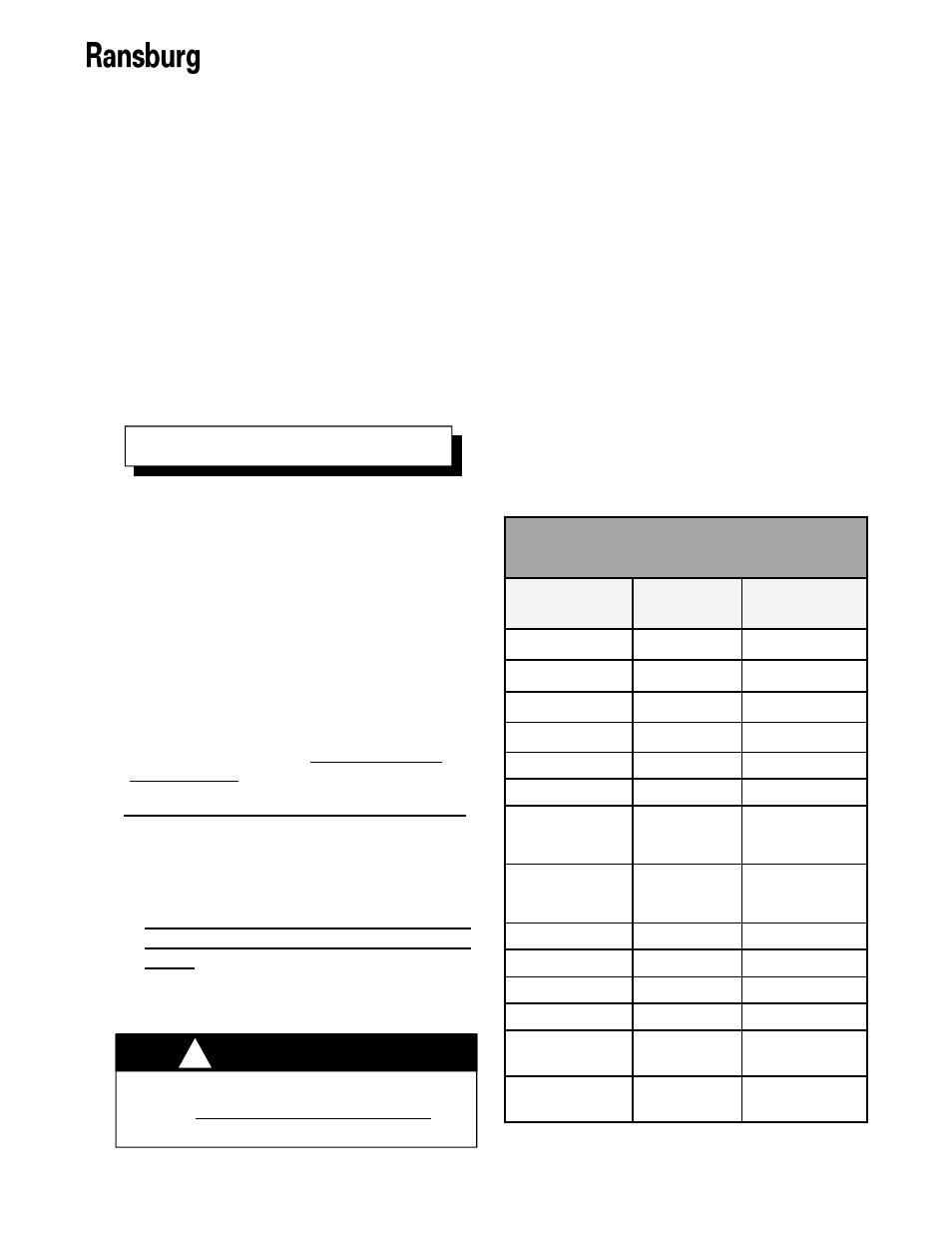
4. Connect the conductors to the respective
remote I/O signal locations. Screw down
the terminal block screws to secure the
conductors in place. The I/O Signal Loca-
tions table contains the complete list of all I/
O, ground, and 24VDC supply locations as
well as their normal voltage/current values.
The locations of the I/O terminal blocks are
shown in Figure 16.
Before performing any wiring, verify the
number of I/O signals, supply, and ground
lines that will be required and select a
shielded I/O cable that has at least that
many lines.
Create a table of I/O signals to con-
ductor wire color. Including the terminal
block location in this table is also helpful
for reference.
Locate all of the required signal termi-
nal connections in advance to determine
the amount of wire length required.
It is better to connect no more than two
(2) conductors into any single terminal
block connection.
N O T E
To operate the Controller in the REMOTE
mode using any number of the discrete I/O
signals, perform the following:
1.
Turn the 9060 Controller off, disconnect
it from its AC source, and remove the
fuses.
2.
Open the Controller cabinet door.
I/O Signal Locations
Signal
Terminal
Block
Local/Remote
TB3-2
Tripleset
(Setpoint 0)
TB3-3
Tripleset
(Setpoint 1)
TB3-4
Reset
TB3-1
HV On
TB2-4
Relay Common
TB2-3
Fault
TB2-2
24 VDC
TB2-1, TB3-10
Trigger
TB3-5
Analog Current
TB3-6
Analog Voltage
TB3-7
Analog Common
TB3-8
Analog Feedback
Current
TB3-9
Ground
TB3-11,
Ground Lug
Normal Value
24VDC
24VDC
24VDC via JTB-1
24VDC
24VDC or GND
24VDC or GND
24VDC or GND
24VDC or GND
24VDC or GND
0-20mA
0-10V
Ground (0V)
0-10V
Ground (0V)