Remote mode external signals, 9060 high voltage controller - installation, Local mode jumper settings – Ransburg 9060 HV Controller 80100-XXX User Manual
Page 30
9060 High Voltage Controller - Installation
25
CP-13-05.3
If a different switch is being used for the
trigger signal, read the switch documenta-
tion for the wiring instructions for the spe-
cific switching element. Verify whether
sinking or sourcing is to be used so the
local/remote trigger protection board
jumpers are set correctly. For further in-
formation, consult your authorized
Ransburg distributor for specific directions
pertaining to your installation or call Cus-
tomer Service.
N O T E
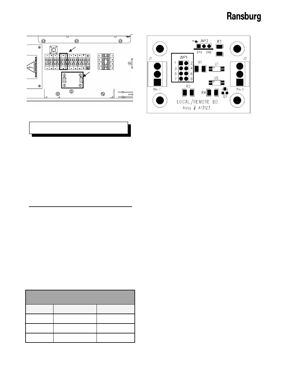
4. The local/remote board (Assy# A13123),
shown in Figure 14 at the bottom below the
remote I/O signal terminal block, is de-
signed for trigger protection in REMOTE
mode. It must have the jumpers adjusted
into “bypass position” to allow for LOCAL
mode operation for the desired input type.
The location of the jumpers on the board is
displayed in Figure 15. Use the LOCAL
mode jumper settings table for the jumper
settings based upon your specific input.
Figure 14: Remote I/O Signal Terminal Block
Trigger Signal - Position 5
Local/Remote Board
Jumper
Local Source
Local Sink
JMP1
1-3
1-3
JMP1
2-4
4-6
JMP2
2-3
1-2
LOCAL Mode Jumper Settings
Figure 15: Local/Remote Board Jumper Headers
Jumper 1
Jumper 2
5. Secure the cabinet door, replace the fuses,
and reconnect the AC source.
For any installation that includes a trigger signal
that is generated by a switch or source that is
external to the 9060 Controller unit, the signal
should be routed in through the standard I/O
connector using a shielded cable (supplied by
user). Secure the cable to the standard I/O
connector as described in “I/O Connections” in
the “Installation” section of this manual so that
the shield of the cable is connected to the
chassis of the enclosure.
REMOTE MODE
EXTERNAL SIGNALS
The REMOTE mode is designed for use with
automatic applicators such as the Estaquick
and Evolver SE where the control of the appli-
cator and Controller are driven by a external
control system using discrete analog and digital
I/O. For example, a programmable logic control-
ler (PLC), can be used as the control system.
There can be up to thirteen (13) or more signal
wires present depending on the signals that are
intended to be used by the control system.
More wires may be needed depending on the
number of power and ground lines required for
any particular installation.