Connection interface, Connectors, 9060 high voltage controller - introduction – Ransburg 9060 HV Controller 80100-XXX User Manual
Page 16
9060 High Voltage Controller - Introduction
11
CP-13-05.3
pressed with the reset button, at the same time,
the screen will display the resettable High
Voltage ON operating hours for 3 seconds on
the display screens.
Preset 2 Button
The Preset 2 Button (in the center below the kV
display) is used by itself to select “Voltage
Preset 2” in the LOCAL operating mode. If
pressed with the reset button, at the same time,
the screen will display the non-resettable High
Voltage ON operating hours for 3 seconds on
the display screens.
Preset 3 Button
The Preset 3 Button (to the right below the kV
display) is used by itself to select “Voltage
Preset 3” in the LOCAL operating mode.
Left (-)/Right (+) Buttons
The left(-)/right(+) buttons in the LOCAL operat-
ing mode are used to modify, decrease and
increase respectively, the currently selected
preset value. If the button is pressed and
released, the preset value is changed by 1 kV
at a time. If the button is held for over a 1/2
second, the value will begin changing by 5 kV
increments.
Reset Button
The reset button is used in LOCAL or REMOTE
operating mode to clear fault or overload
conditions when the trigger signal is OFF. This
will NOT prevent any other active fault condi-
tions from triggering a new fault.
HV Control Button
This button, shown in the center of Figure 3, is
not used
to perform mode changes.
It is
reserved
for future use. The unit defaults to
LOCAL mode. To enter REMOTE mode, a
remote I/O signal input, local/remote mode
selection, indicates when the unit should be in
REMOTE mode. When this remote I/O signal is
active, the unit will be in REMOTE mode,
otherwise the unit will be in LOCAL mode.
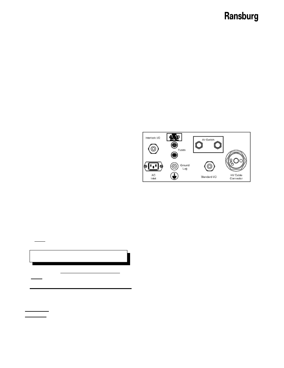
CONNECTION INTERFACE
The 9060 Controller connection interface shown
in Figure 4, provides all of the required connec-
tions for setting up either a remote I/O con-
trolled painting system or a local controlled
painting system. This connection interface
consists of one (1) high voltage cable connect-
or, one (1) standard I/O connector, one (1)
interlock I/O connector, one (1) ground lug
connection, one (1) optional air flow switch
connection, two (2) fuses, and one (1) AC inlet
receptacle.
Figure 4: 9060 Connection Interface
CONNECTORS
High Voltage Cable Connector
The high voltage cable connector is the largest
connector and is located on the far right of the
connection interface. The connector will come
covered with a factory installed red protective
cap. This connector is designed for use with
standard high voltage cables such as A10560,
79518, and 79519. The specific cable required
depends on the applicator being used. Please
refer to the applicator manual for the cable
required.
Standard I/O Connector
The standard I/O connector is located just left
of the high voltage cable connector. This
connector is provided as the entry point for a
shielded multi-conductor cable used for remote
I/O signals and includes the required cable
grommet hardware to keep the cable in place
with minimal strain. For more information on
remote I/O signal wiring, see the “Installation”
section of the service manual.
There is a 5 second fault reset delay
timer that inhibits the triggering of high
voltage immediately after a fault reset.
N O T E