Kasco Marine Quick Disconnect User Manual
Page 2
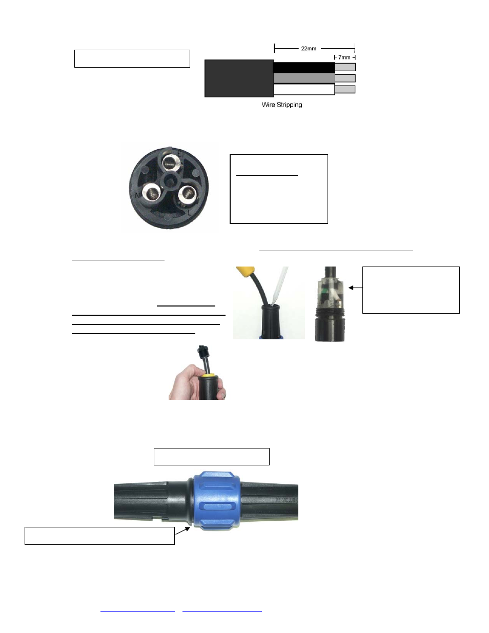
Step 3: Prepare the cable and strip wire ends as shown in figure 4.
Step 4: Insert the stripped wire ends into the terminals on the back of the Pin/Socket insert and fully
tighten the wire retention screws.
(Refer to Figure 5 for correct wire orientation.)
After the wires have been connected securely, pull the cable and insert back into the housing and tighten
with a screwdriver to ensure the insert is seated correctly. Note: LEFT HAND THREAD, turn the insert
counter clockwise to tighten.
Step 5: Using the Black Potting Resin, apply
enough resin into the housing to cover the
wires and contacts. The resin should be about
1/8” onto the cord jacket. Note: Adding too
much resin will cause excess to be forced into
female end of the pin connector, preventing
proper connection of the two halves.
Step 6: Slide the gland and
gland nut along the cable into
the body and tighten
the gland nut securely.
Repeat Steps 1 through 6 to assemble the remaining half of your quick disconnect assembly.
Once the two subassemblies have been completed, they can be joined together. Plug pin assembly into the
socket assembly and tighten the large blue nut securely. The blue nut should be hand tightened only.
(See figure 6)
Figure 5:
Wire Connections
Black wire to terminal L
White wire to terminal N
Green wire to terminal E
Note: There is a small gap after tightening
Figure 6: Tightened Assembly
Figure 4: Wire stripping Detail
Cut-Away disconnect
shown with clear resin.
Note amount that is
covering cord jacket.
For seasonal removal, your quick disconnect includes an optional water tight cover. Simply separate the
quick disconnect and insert the sealing cover into the large blue nut half and tighten firmly.
Kasco Marine, Inc.
800 Deere Road, Prescott, WI 54021-1241
Phone (715) 262-4488
•
Fax (715) 262-4487
www.kascomarine.com
•
Rev 6 12-18-2006