Farm Star HK-202 User Manual
Page 7
5
6
A S S E M B LY
(continued)
Then place the forward end of the lift arm between the
two (2) inside pull bracket ears. Slide the pull pin in fur-
ther so that it goes through the ball end of the lift arm and
enters the hole in the inside pull bracket ear.
Rotate the pull pin so that the holes in the pin are hori-
zontal. Slide the spacer tube and adjust the pull pin so
that a large (
5
/
16
”) hairpin clip can be inserted through the
center hole of the pull pin. This locks the pull pin in place
on each side.
Insert the rocker arm extensions into the rocker arm
socket. Place the lock plate at the backside of the rocker
arm extensions and bolt in place with the
3
/
8
” – 16 x 1”
hex head bolts. The holes in the rocker arm extensions
should be parallel to the ground.
Pin the two (2) lift arm leveling assemblies (ref. #16 thru
#20) to the ball ends on the rocker arm extensions. Use
the two (2) upper lift pins (ref. #21).
Raise the lift arms, sliding them between the clevis ends
of the lift arm leveling assemblies, and pin them in place.
Install the stabilizer stub pins (ref. #27) in the forward
holes of each lift arm. Have the large (
7
/
8
”) diameter of the
stub pin to the outside of the lift arm and the threaded nut
to the inside. Do not use a lockwasher under the nut.
Place a screwdriver or small bar through the linchpin
hole and tighten the nut on the stub pin.
Place one end of the stabilizer bars (ref. #16-19) over
the ends of the pull pins on the outside of the pull bracket
and secure with linchpins.
The stabilizer bars have threaded ends and can be
adjusted to the correct length by turning the center
barrel. Adjust the stabilizer bars, then slide the other end
over the stabilizer stub pins in the lift arms. Secure in
place with linchpins.
Attach the center link (or toplink) to the tractor toplink
brackets using the
3
/
4
” toplink pin and linchpin provided.
Tighten all bolts before using this kit.
Replace the swinging drawbar on your tractor.
NOTE: There may be some operations or implements
where it is best to operate the tractor with the swinging
drawbar removed.
Check to make sure that the hitch is operating smoothly.
Read manual before operating.
I N S T R U C T I O N S
(continued)
I N S T R U C T I O N S
(continued)
NOTE: Angle of Stabilizer Ends
The ends of the stabilizer bars (ref. #17, 18) may not be
at the correct angle for your hitch. Since this hitch kit can
connect to either Category I (26” pull pin width) or to
Category II (32” pull pin width) equipment, slightly differ-
ent angles will be required on the stabilizer bar threaded
stub ends. If the angle is not correct for your desired hitch
spacing, place one end of the stabilizer bar threaded
stub in a vise and apply hand pressure to the other end
of the stabilizer bar assembly until desired angle is
obtained. Reverse the stabilizer assembly in the vise and
repeat for the other end.
It is suggested that you connect the lift arm ends to a
piece of equipment or install a 3 pt. drawbar and center
the lift arms (side to side) so you can easily determine
what angle correction may be required.
NOTE: Use of Stabilizer Bars
For some implements such as post hole diggers, rear
blades, landscape rakes, and rear 3 pt. scoops, you
need to install the stabilizer bars to eliminate side
movement of the hitch to control the implement.
With other implements, such as 3 pt. plows, disc
harrows, field cultivators, and harrows, it is best to
remove the stabilizer bars and allow the hitch side
movement. This makes it easier to steer the tractor and
minimize side pressure on the hitch and the implement
when turning.
NOTE: When connecting the hitch to an implement, it will
be necessary to remove the lift arm end of the stabilizer
bar from the lift arm. This allows the lift arm to swing out
and be installed on the pull pin of the implement.
After the lift arms are connected to the implement, the
stabilizer bars need to be reconnected and adjusted so
that the implement is centered behind the tractor.
W A R N I N G !
▲
Keep clear of rotating parts; stay on tractor seat
until all motion has stopped.
▲
Be sure tractor engine is off and key is removed
before making any adjustments.
▲
Do not get under machine to make measurements
or adjustments without securely blocking imple-
ment first.
A heavy load can cause instability in driving a trac-
tor. Make sure the front of the tractor is properly
counter-balanced with weights. Always drive slowly
– especially around turns. An unstable tractor could
steer badly and possibly tip over, causing injury or
death.
W A R N I N G !
O P E R AT I O N
Two holes are provided on the lift arms to connect to the
lower ends of the leveling assemblies.
The forward holes will provide the greatest lifting range
for the ball ends of the lift arms. The rear holes will allow
heavier loads to be handled by the hitch.
The adjustable screw type leveling assemblies will
provide additional adjustment in the lifting height of the
hitch.
NOTE: BE SURE THAT AT LEAST 1
1
/
4
” OF THREAD
ON EACH END IS ENGAGED INTO THE THREADED
BARREL OF THE LEVELING ASSEMBLIES.
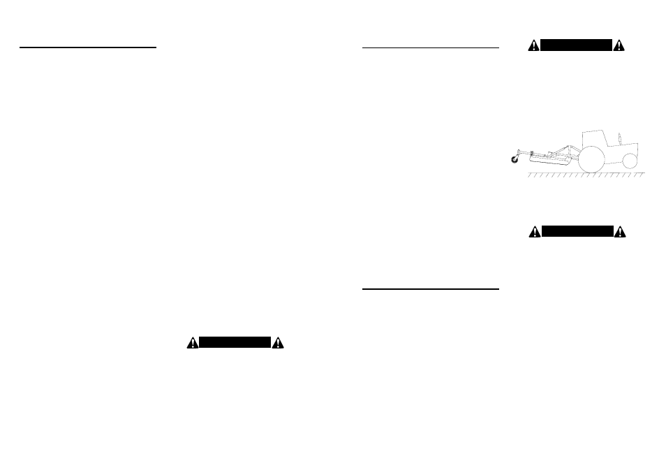
Figure 1.
Tractor Stability
W A R N I N G !
When using 3 pt. hitch equipment, a minimum 20%
of tractor and equipment weight must be on tractor
front wheels. Without this weight, tractor could tip
up, causing possible loss of control and possible
personal injury or death. The weight may be attained
with a front end loader, front wheel weights, ballast
in tires or front tractor weights. When attaining a
minimum 20% of tractor and equipment weight on
the front wheels, you must not exceed the ROPS
weight certification. Weigh the tractor and equip-
ment. DO NOT GUESS OR ESTIMATE!
S A F E T Y T R A I N I N G
• Know your controls and how to stop tractor, engine,
and PTO quickly in an emergency. READ THIS
MANUAL AND THE ONE PROVIDED WITH YOUR
TRACTOR.
• To avoid accident or injury, do not allow anyone to
operate this equipment without proper instructions.
Any person who operates this equipment must be
instructed in and be capable of the safe operation of
the tractor, implement and all controls.
• Do not allow children to operate this machine.
• Always wear relatively tight and belted clothing to
avoid entanglement in moving parts. Wear sturdy,
rough-soled work shoes and protective equipment for
eyes, hands, and hearing. Never operate tractor in
bare feet, sandals, or sneakers.
• Operate only in daylight or good artificial light.
• Ensure implement is properly mounted, adjusted and
in good operating condition.
• Ensure that all safety shielding and safety signs are
properly installed and in good condition.
The adjustable screw type top link can also be short-
ened or lengthened to adapt different implements and
can be used to obtain various degrees of pitch on the
implements you are using.
The ball sockets on the lift arms are two-way balls, so
they will accommodate both Category I or Category II lift
pins on the implement. If the drawbar or implement has
Category I (
7
/
8
”) pins, make sure the balls are turned so
that the
7
/
8
” diameter holes are used.