Farm Star ES-33 User Manual
Page 8
8
I N S T R U C T I O N S
(continued)
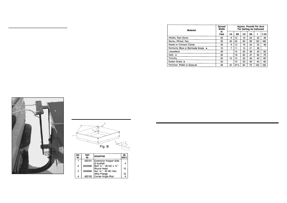
The spread width indicated on this chart is possible if spinner is operated 30 inches above the
ground. Seeder should be level or tilted forward slightly.
NOTE:
Spread Chart settings are approximate – always make trial run to check actual application rate.
The amount of seed or fertilizer broadcast depends on the size of the hopper opening and the speed of the tractor.
The table shown is an approximate guide based on a tractor speed of 4 MPH, so adjust for different speeds.
.
NOTE:
Since there is no agitator in the seed hopper, these materials will bridge at narrow seed gate settings and
cause erratic seeding rates. If bridging occurs at wider seed gate settings, cleaning the seed or blending with
a small dense seed such as clover may help. A mix of dry sand with the seed (50/50 mix) can sometimes solve
the problem.
H E L P F U L T R O U B L E - S H O O T I N G T I P S
1. Not feeding even –
A. Seed gate opening may be set too close for the
material being spread. To overcome, set the open-
ing larger and driver faster to obtain same spread
rate.
B. Check material for foreign matter or lumps.
D. Set screw loose or missing on fan hub.
E. Too windy for material being spread.
F. Agitator problems – check tips above, under “Not
feeding even.”
G. Operator not spacing spread runs properly for
correct overlap.
For best results, cover area twice over at one-half
recommended material usage rate, the second
time over to run halfway between first spreading
width or in a criss-cross pattern. This method
allows the most complete and even coverage, as
well as to give operator a chance to adjust gate
setting to compensate for too thin or too heavy a
covering the first time over.
2. Poor spread –
A. Too much speed (over 560 PTO rpm) can cause
uneven spread.
B. Spreader fan speed too slow (under 520 rpm) will
result in a narrow spread.
C. Bent or broken fan blades.
O P E R AT I O N A L S P R E A D I N G C H A RT
(Calibrated at 4 MPH ground speed)
7
OPTIONAL ES-1.5 PKP
R O P E C O N T R O L PA C K A G E
I N S T R U C T I O N S
Install the
1
/
4
” rod connecting link between the scale
plate lever (use the unused hole in the lever) the lower
pivot arm of the rope control pivot. Install the
3
/
32
” cotter
pins in each end of the connecting link and spread the
cotter pins.
Order part number 480040 for the optional rope pull
bracket assembly.
Tie one end of the rope to one end of the upper pivot
arm and the other rope to the other end of the pivot arm.
Separately run the ropes to the cab of the pickup. If the
pickup has a sliding rear window, the rope can be run
through the window.
The ropes can also be run along the left side of the
pickup and looped around the side mirror bracket. This
will allow operator control by reaching through the open
side window.
NOTE: If the ropes are located to the side mirror, a
simple loop with some slack in the rope will allow the
operator to easily remove the loop from the side mirror
bracket for easy access in and out of the left door.
NOTE: Cut off any additional length of rope not
required and make sure no ends of the loop can catch in
brush or tree limbs. Damage to the seeder and rope
control could occur.
I N S T R U C T I O N S
(continued)
OPTIONAL USX-3
3 BU. EXTENSION KIT
R E PAIR PA RT S
Fig. A
This optional package allows operators to open or
close the seed gate of the ES-1.5 PKP seeder from the
cab of the pickup truck.
One rope will open the seed gate when pulled and the
other will close it.
Refer to figure “A” to see the relationship of the rope
control frame to the seeder.
The rope control frame mounts on the front side of the
2” seeder mount tube with the same
1
/
2
” x 3
1
/
2
” hex bolts
that hold the seeder.
NOTE: Make sure the rope control lower pivot arm is
on the same side as the scale plate assembly of the
seeder before bolting in place.
NOTE: The rope control bracket may come up against
the forward top edge of the seed hopper. There should
be a slight space between these parts. If necessary,
remove the rope control bracket and install two or three
1
/
2
” flat washers between the backside of the rope control
bracket and the 2” mounting tube.
Extra
1
/
2
” flat washers are included with the rope control
bracket in case they are needed.