Instructions – Farm Star 500 W User Manual
Page 5
T
T R
R A
A C
C T
T O
O R
R R
R E
E Q
Q U
U I
I R
R E
E M
M E
E N
N T
T S
S
A
A N
N D
D P
P R
R E
E P
P A
A R
R A
A T
T I
I O
O N
N
The Model 500 3-pt. mounted post hole digger will fit most
Category I, Category II and some larger Category 0 tractors
equipped with a standard 3-pt. hitch.
NOTE: Some Category 0 tractors have very short lift arms or
5
/
8
” diameter (Cat. 0) lift arm ball ends. These tractors are not
usually suitable for post hole digging operation.
Check the tractor’s 3-pt. hydraulic lift system. It should oper-
ate up and down smoothly and have enough power to lift the
dirt-loaded auger out of the hole. Refer to your tractor opera-
tor’s manual or dealer for any adjustments necessary to put the
3-pt. hydraulic lift system in good working order. (I&T shop
manuals will list most specifications and adjustment instruc-
tions - available from most farm equipment dealers.)
Check the shield over the PTO stub shaft. Make sure it is in
good condition and bolted securely to the tractor. Purchase a
new shield if old shield is damaged or missing.
Tractor must be equipped with stabilizer bars, adjustable sway
chains, or sway blocks to keep the post hole digger from swing-
ing side to side.
Smaller size tractors may need front counter weights to
counter-balance the weight of the post hole digger and the
weight of the dirt on the auger.
It is recommended that the tractor be equipped with a
Rollover Protection System (ROPS) and a seat belt that is
used.
Be sure your tractor is in good condition. Read all the
safety precautions and make sure all tractor operators are
familiar with the safety rules of operation.
A
A S
S S
S E
E M
M B
B L
L Y
Y A
A N
N D
D M
M O
O U
U N
N T
T I
I N
N G
G
Unpack all the bundles and lay out various parts. Start with
the yoke (Ref. #4). Place the pull pins (Ref . #5) through the
holes in the legs of the yoke and secure with nuts and lock
washers.
NOTE: If your tractor lift arm spacing is 32”, place the pull pins
on the outside of the yoke legs as shown in the diagram. If your
tractor lift arm spacing is 26” or less, then place the pull pins
on the inner side of the yoke legs. The pins are Category I (
7
/
8
”
dia.). If your tractor is Category II, then lift arm bushings are
required to properly fit the 1
1
/
8
” dia. Cat. II lift arm balls.
(Bushings not supplied.) Place the lift arms of your tractor over
the pull pins in the yoke and secure with linchpins (not sup-
plied).
Pin end of digger boom (Ref. #1) to tractor toplink bracket.
Raise boom by hand – check that it doesn’t hit any part of
toplink bracket (some tractors only). If problem exists, change
hole location and re-check. Failure to check can result in
boom damage. Cat. I tractors need bushing. Connect yoke to
boom with pin (Ref. #13) and cotter pins.
7
4
INSTRUCTIONS
C A U T I O N !
NOTE: Always use adapter bushings when using Category I
pins on a Category II hitch. Trying to use Cat. I pins in a Cat.
II hitch without bushings will result in a very sloppy fit and the
post hole digger will be unstable.
NOTE: When attaching the yoke to the boom, use the hole in
the adjustment channel best suited for your tractor. If you don’t
know the best hole location, start with the middle hole.
Install shields on input and output ends of gearbox. A socket
with a long extension is the best tool for easy installation. The
shield with two large holes (Ref. #22) is for the output end of the
gearbox. Check exploded parts drawing for correct position.
NOTE: It is easier to install the guards on the gearbox before
installing the gearbox on the post hole digger.
Do not operate this equipment without shields properly
installed. This is for your protection, and the manufactur-
er recommends the use of these shields at all times while
operating this post hole digger.
Attach the gearbox (Ref. #14) to the boom using the gearbox
hitch pin (Ref. #13) and secure it with the two cotter pins (Ref.
#7). The gearbox should be placed so that the large shaft is
pointing toward the ground and the small shaft is pointing
toward the tractor.
NOTE: The gearbox is shipped WITHOUT lubricant, so it will
be necessary to fill it before use. With the gearbox in a level
position, fill to the side inspection hole with a good 90 wt. gear
lubricant. Check often and add lubricant if necessary.
Grease the input shaft of the gearbox before installing the
PTO shaft. This reduces the chance of the PTO shaft yoke
from galling to the input shaft if the shear pin should break.
Slip the two telescoping ends of the PTO shaft together.
Place the unsplined end on the gearbox input shaft and bolt it
in place with the
5
/
16
” shear bolt (Ref. #15) and secure it with the
lock washer and nut.
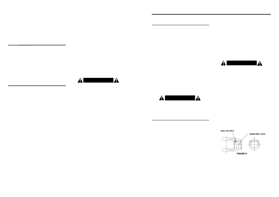
On the implement end or the PTO shaft there is a hole in the
yoke just forward of the
5
/
16
” shear bolt (see Figure A). This hole
is for the
3
/
16
” diameter x 1
1
/
4
” long roll pin (#2504011). When
this roll pin is driven in this hole, the center of the roll pin
engages into the groove on the front of the gearbox input
shaft. This prevents the PTO assembly from coming off if
C A U T I O N !
3. Universal joints should be greased after digging 150 holes.
Telescoping parts must be kept clean and lubricated.
4. Check bolts and pins daily. Check auger teeth and teeth
mounting bolts more often if digging in rocky soil conditions.
5. Make sure PTO driveline yoke and gearbox input shaft are
clean and free of burrs. Keep well lubricated to prevent
galling of yoke and input shaft when shear bolt becomes
sheared.
6. Keep all shields in place. Order new shields if damaged or
missing.
7. Keep cutting edges sharp. Sharp cutting edges dig easier
and better. Outer cutting edges on larger augers wear
faster than inner cutting edges; switching teeth will even
wear.
P
P O
O S
S T
T H
H O
O L
L E
E D
D I
I G
G G
G E
E R
R O
O P
P T
T I
I O
O N
N S
S
1. Heavy Duty Augers: Augers with heavier flighting and a
reinforced drive tube are available for rocky or tough soil
conditions. Check with dealer for availability.
2. Heavy Duty Fishtail Center Point: Recommended for
tough or rocky soil conditions. The fishtail point will work
around smaller rocks. Order part #170802.
3. 12” Auger Extension: Available for situations where deep-
er holes are required. NOTE: Smaller tractors may not
raise auger high enough to clear hole when 12” auger
extension is used. Order part #170700.
4. Hydraulic Down Force Kit: For tough, hard soil conditions.
This will allow operator to put 300-400 lbs. of down force on
the auger to force cutting edges into tough or hard ground.
Tractor must have auxiliary hydraulic outlet. Order part
#170810 for Model 500 Post Hole Diggers.
T
T R
R O
O U
U B
B L
L E
E -
- S
S H
H O
O O
O T
T I
I N
N G
G G
G U
U I
I D
D E
E
PROBLEM: AUGER WILL NOT DIG
Possible Solutions:
• Teeth dull - sharpen or replace.
• Ground too dry and hard - order optional fishtail point
(#170802) or optional down force kit, or wait until it
rains.
• Auger turning too fast and bouncing - reduce speed.
• Tall grass has wrapped around auger teeth - remove.
• Auger encountering rocks, roots, or other obstruction -
lift auger from hole and inspect.
• Auger teeth improperly positioned - see operator’s
manual for proper tooth pattern.
PROBLEM: AUGER DIGS SO FAR, BUT WILL NOT
DIG DEEPER
Possible Solutions:
• See solutions for #1 above.
• PTO assembly “bottoms out,” not allowing digger to
lower - remove auger from digger and lower digger.
Gearbox should lower to the ground; if not,PTO drive-
line assembly may need to be shortened.
• PTO driveline interferes with swinging drawbar - swing
drawbar out of the way or remove.
• Tractor hydraulic system may be faulty - consult tractor
dealer.
• Soil could have hardpan layer 6”-10” below surface -
use optional fishtail point (#170802) or optional down
force kit (see list of optional equipment).
PROBLEM: POST HOLE DIGGER SWAYS SIDE TO
SIDE
Possible Solutions:
• No sway bars or sway blocks on tractor- add same.
• Lift arms not adjusted evenly - adjust lift arms.
• Post hole digger is mounted with excessive looseness
in the hitch connecting points - use proper size pins or
bushings
.
PROBLEM: BENT AUGER FLIGHTING OR BENT
AUGER
Possible Solutions:
• Tractor moved while auger was turning in hole -
always set brakes on tractor and make sure it is out
of gear.
• Operator moved tractor with auger in hole to try and
straighten a hole being dug at an angle.
• Auger is encountering rocks or roots or other foreign
objects - remove object from hole or change location.
• Outer edge of auger flighting is bending due to contact
with rocks or roots - use heavy duty auger with thicker
flighting.
• Shear bolt has been replaced with harder bolt - replace
with Grade 2 bolt per instructions.
PROBLEM: AUGER SCREWS ITSELF INTO THE
GROUND
Possible Solutions:
• Operator did NOT ease 3-pt. hitch to ground slowly.
• Faulty 3-pt. hitch hydraulic system on tractor.
• Draft control is not in OFF position.
• Tractor is too small to handle digger.
PROBLEM: PTO DRIVELINE ASSEMBLY COMES
OFF INPUT SHAFT OF GEARBOX WHEN
SHEAR BOLT IS SHEARED.
Possible Solution:
• Roll pin missing in yoke at gearbox input shaft. Install
roll pin as per instructions.
THIS IS A DANGEROUS SAFETY HAZARD, CORRECT
IMMEDIATELY!
PROBLEM: PTO DRIVELINE FAILURE
Possible Solutions:
• Operator raising post hole digger too high above
ground when PTO is engaged - causes excessive PTO
joint operating angle.
• PTO is engaged while moving between holes. (Auger
swings, which causes excessive PTO joint operating
angle.)
• Improper use of a hard shearbolt - use Grade 2 bolt per
instructions.
• Driveline has not been properly lubricated.
• Engaging tractor PTO with engine at high rpm.
• Digging holes too deep so that PTO driveline contacts
ground.
• Operating at high rpm.
• Use of auger extension can require post hole digger to
be lifted high, which can cause excessive PTO joint
operating angle.
PROBLEM: PTO DRIVELINE “GALLS” OR “FRIC-
TION WELDS” TO INPUT SHAFT OF
GEARBOX
Possible Solution:
• No lubrication on input shaft of gearbox to allow yoke
of PTO driveline to turn freely on input shaft when
shear bolt is sheared.
Always keep input shaft
greased.
PROBLEM: GEARBOX FAILURE
Possible Solutions:
• No oil in gearbox.
• Oil not changed per instructions.
• Shear bolt has been replaced with a harder bolt -
replace with Grade 2 per instructions.
• Bent output shaft is due to operator moving tractor
when auger is in hole
.
W A R N I N G !