Blagdon Pump X50 Metallic User Manual
Page 13
HG-CF-1099 Rev. Q – 05.09.13
Page 13
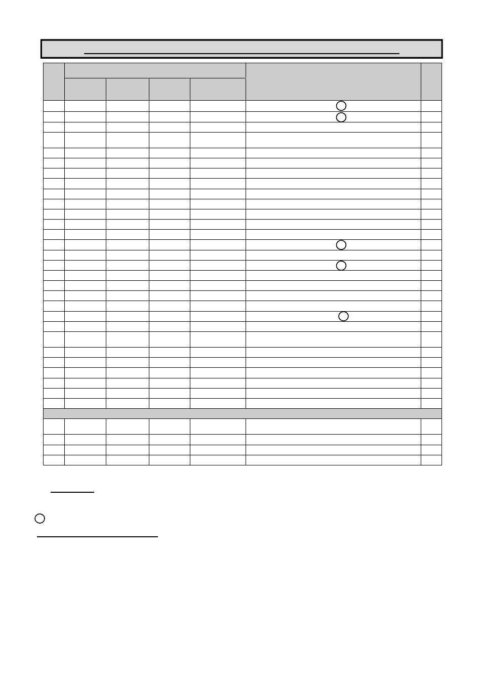
Wet Side Parts List - (Ref. Nos. are common to all models, pages 12)
PART NUMBER
DESCRIPTION
QTY
REF
No.
ALUMINUM
(COMMON)
CAST IRON
STAINLESS
STEEL
HIGH
TEMPERATURE
1
A041
-
A042
-
BOLT - HEX. HD.
M8 x 30
16
2
A005
-
A040
-
BOLT - HEX. HD.
M8 x 35
16
3
C013
-
C044
-
WASHER
M8
16
4
50-255
50-274
50-260
50-032
50-130
-
-
DISCHARGE MANIFOLD - BSP
DISCHARGE MANIFOLD - NPT
1
1
5
SEE TABLE
-
1B109
-
VALVE BALL
4
6
SEE TABLE
-
-
-
O-RING (METALLIC SEATS ONLY)
4
7
SEE TABLE
-
SEE TABLE
-
VALVE SEAT
4
8
SEE TABLE
-
-
-
O-RING (METALLIC & PTFE SEATS ONLY)
4
9
SEE TABLE
-
-
-
O-RING (METALLIC SEATS ONLY)
4
10
B507
-
B508
-
FLANGED NUT - SERRATED
M10
24
11
1B026
1B073
50-303
-
INNER COVER
2
12
D028
-
D310
-
SOCKET CAP SCREW
M8 x 25
12
13
SEE TABLE
-
-
-
DIAPHRAGM
2
14
A151
-
A145
-
BOLT - HEX. HD.
M10 x 45
24/16
15
B505
-
B506
-
FLANGED NUT - SERRATED
M8
16
16
A496
-
-
-
BOLT - HEX. HD.
M10 x 100
8
17
1B015
-
-
1B177
BUMP STOP
2
18
1B021
-
-
-
BACKPLATE
2
19
1B054
-
-
1B003
SUPPORT DIAPHRAGM
2
20
1B039
-
-
-
DIAPHRAGM - PTFE OVERLAY
2
21
SA10042
SA10044
SA10044
-
FRONTPLATE ASSEMBLY
2
22
50-253
50-258
50-052
-
OUTER COVER
2
23
50-254
50-265
50-259
50-033
50-129
-
-
SUCTION MANIFOLD - BSP
SUCTION MANIFOLD - NPT
1
1
24
SP475
-
-
-
NAMEPLATE
1
25
-
-
1B034
-
BASE LEG CAP
4
26
-
-
50-074
BASE LEG
2
27
C165
-
C173
-
WASHER - SPRING
M8
4
28
D490
-
D372
-
SOCKET CAP SCREW
M8 x 16
4
Atex models only :-
31
1A060
-
-
-
NAMEPLATE - SERIAL NO./MODEL NO.
(REPLACES ITEM 27)
1
32
SA10528
-
-
-
GROUNDING LEAD ASSEMBLY
1
33
SP467
-
-
-
ATEX NAMEPLATE
1
34
SP474
-
-
-
TIE-LOK TIE
1
A
C
C
B
B
- Wet Side Kits - These items are available in a recommended spares kit. Please refer to matrix on page 16 for details on part numbers
for ordering purposes or refer to your local stockist / distributor for further details.
Note! Wet Side Kits only include valve seats if the original parts were rubber :- i.e. Buna-N, Neoprene etc.
Indicates Torque setting required. See page 11 for details.
HIGH TEMPERATURE INSTALLATIONS
In situations where the temperature of the fluid to be pumped is likely to exceed 100°C, a high temperature pump code must be specified. This
is signified using an ‘X’ in the last part of the pump code as shown.
“XTS” in place of “TTS”. Reference Pump Code matrix on page 3
This indicates the following specification amendments :-
Diaphragm shaft seals will be changed from Polurethane to Viton. Back-up diaphragms and any bumpstops will be changed to Viton. In
extreme cases only, any gaskets could be changed to a higher temperature spec., and the diaphragm shaft bushes could be changed from
plastic to metal.
Refer to main table above and on page 14 for quantities / pump.
B