General Technologies TA300 SmarTach D : Digital Diesel Engine Tachometer User Manual
Page 5
Page 8
Page 7
4- While holding the (Trigger Level Adjust) button pressed, use the
(Sensitivity
Adjust increase) or (Sensitivity Adjust decrease) buttons to adjust the % value.
Notes:
• Adjusting the trigger level of the TA300 while performing RPM measurements, provides
quick feedback on how this setting affects the response of the TA300 in any given
situation.
• The trigger level can be adjusted between 20% and 80%. The default value for the
trigger level is 50%.
• For example, if the trigger level is set to 70%, the TA300 will register an engine cycle
when the signal level from the piezoelectric sensor reaches or exceeds 70% of the
maximum signal.
• Higher trigger levels increases the noise rejection, and lower trigger level will help in
measuring RPM when dealing with inconsistent injection pulses. For most cases the
default 50% level is the optimal value.
• The values set by using the Trigger Level Adjust function are stored in internal memory,
and will be retained even if the instrument is powered off, the battery is depleted or
is removed.
4. APPLIcATION INFORMATION
4.1 Using the piezoelectric sensor
Important
The piezoelectric sensor is constructed with an special piezoelectric
ceramic material and it can be easily damaged by impacts or if excessive
pressure is applied.
1- For the piezoelectric sensor to work, it requires that a good electrical connection be
established between the center part of the sensor, and the ground clip. This can be
achieved in two ways:
• Fit the piezoelectric sensor to a clean unpainted section of an injection line. Then
connect the ground clip to that same clean section of the injection line as shown in
Fig. 3. or to a convenient ground in the engine. If necessary scrape and sandpaper
the line in order to expose the metal surface.
• If you do not wish to scrape the fuel line, you could tightly wrap a piece of aluminum
foil around the pipe and clamp the piezoelectric sensor over this foil. Make the foil
wrap long enough to allow placing of the ground clip on the same piece of foil. Use
of aluminum foil will often fix problems due to bad electrical connections between
the piezoelectric sensor and the injection pipe and ground clip.
2- Do not over tighten the clamp. Use of excessive force or tools such as pliers to tighten
the clamp will result in damage to the piezoelectric sensor and void the guarantee.
3- If not already connected, locate the forked terminal at the end of the red wire (near
to the alligator ground clip) and push it under the flat head of the connector pin at the
corner of the piezoelectric sensor. This connector pin is the one with a coil spring. You
will see that this spring presses a conical washer against the flat pin head. The forked
terminal must be inserted between this washer and the flat pin head. Hook up is now
complete.
4.2 Troubleshooting
The main factors that may cause unstable, erroneous or in some cases prevent the TA300
from obtaining a reading at all are:
• Poor electrical contact between the center of the piezoelectric sensor and the
ground clip.
• Engine/fuel line vibration.
• Weak signal due to the characteristics of the fuel line or the fuel injection
pump.
4.2.1 Poor electrical contact
Please refer to ‘4.1 Using the piezoelectric sensor’ for detailed instructions on how to use
the sensor.
4.2.2 Engine/fuel line vibration
The piezoelectric sensor is specially designed to detect the expansion of the fuel line cause
by the pulses of pressure generated by the fuel when injected into the cylinder. However
under some conditions the vibration of the engine and fuel line may cause an excessive
amount of noise in the signal, in which cases the TA300 may not recognize the signal and
generate incorrect RPM readings or no reading at all.
Possible solutions:
• Use the Trigger Level Adjust function to change the trigger level until a stable RPM is
obtained.
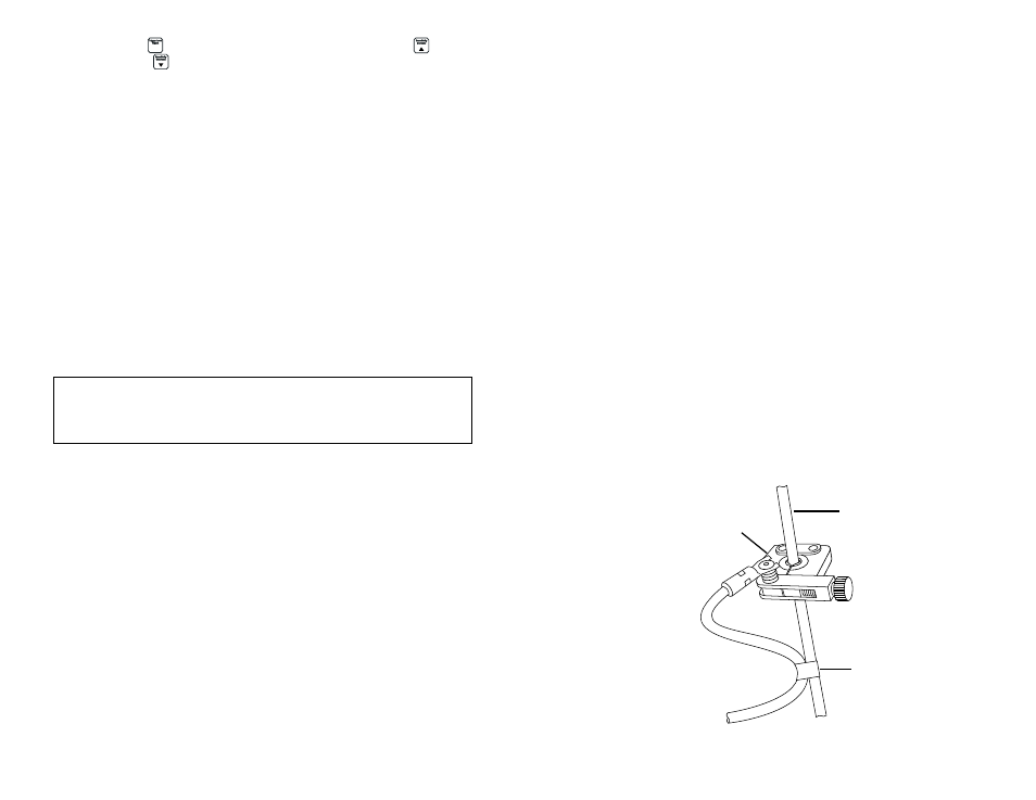
• Sometimes the vibration noise may be caused or magnified by the minute ‘jerking’ of
the cable connecting to the piezoelectric sensor to the TA300, and providing some
strain relief may be of help in obtaining RPM readings. To provide strain relief to the
piezoelectric sensor, attach the red wire (which is connected to the sensor ) to the
same fuel line using electrical tape or a cable tie, as shown in Fig 4.
Fig. 4 - Strain relief setup for piezoelectric sensor
Fuel injection line
Piezoelectric sensor
Electrical tape or cable tie