General Technologies TA300 SmarTach D : Digital Diesel Engine Tachometer User Manual
Page 4
Page 6
Page 5
• The first time the Sensitivity Decrease button is pressed, the display will show
the sensitivity setting, each time the button is pressed again it will decrease the
signal sensitivity of the TA300. A few seconds after the button is released the
display will resume to show Maximum and Minimum readings.
3.4 Measurement Procedures
3.5 Additional functions
3.5.1 Minimum and Maximum functions
The TA300 maintains a continuous record of the minimum and maximum readings shown
on the display.
• The minimum and maximum values are reset upon turning the TA300 power on, or by
momentarily pressing the
(Power On/Off and Reset) button.
• For the tachometer function (RPM) all readings are shown in 10s of RPM, so to obtain
the actual values, the minimum and maximum values should be multiplied by 10.
3.5.2 Sensitivity Adjust function
The TA300 allows the user to adjust the level of signal sensitivity it can detect, in order to
match a wide variety of fuel pressures and fuel lines characteristics.
To use the Sensitivity Adjust function:
1- Turn the instrument on.
2- To perform adjustments of the signal sensitivity while performing actual measurements,
follow the procedure as described in ‘3.4 Measurement procedures’.
4- The first time the Sensitivity Increase or the Sensitivity Decrease button is pressed,
the display will show the sensitivity setting, and each time the button is pressed again
it will increase or decrease the signal sensitivity. A few seconds after the button is
released the display will return to show Maximum and Minimum readings.
Notes:
• Adjusting the signal sensitivity of the TA300 while performing RPM measurements,
provides quick feedback on how this setting affects the response of the TA300 in any
given situation.
• Signal sensitivity can be adjusted between 1 and 10. The factory calibration
value is 5.
• The lower the value of the sensitivity setting the bigger the signal input needs to be for
detection by the TA300, and converserly higher sensitivity settings can detect smaller
signals input.
• The values set by using the Sensitivity Adjust function are stored in internal memory,
and will be retained even if the instrument is powered off, the battery is depleted or
removed.
3.5.3 Trigger Level Adjust function
The TA300 also allows the user to adjust the trigger (or threshold) level it uses to measure
RPM from the signal it receives from the piezoelectric sensor. This feature can be used to
compensate for excessive noise in the signal generated by vibration, electromagnetic in-
terference or particular characteristics of fuel pressure, injection patterns and fuel lines.
To use the Sensitivity Adjust function:
1- Turn the instrument on.
2- To perform adjustments of the trigger level while performing actual measurements,
follow the procedure as described in ‘3.4 Measurement procedures’.
3- Press and hold the (Trigger Level Adjust) button until the minimum reading in the
display is replaced by a number followed by a ‘%’ sign.
CAUTION
To avoid personal injuries and damage to the instrument carefully inspect the
fuel injection lines and fuel pump for damage or leaks, and avoid using this in-
strument in case any damage or leaks are found. Never touch the piezoelectric
sensor during a test. Wear insulating gloves when working around high volt-
age, and hot parts, and keep away from moving parts (fan, drive belts, etc)
and hot objects (exhaust manifold and pipes, muffler, catalytic converter, etc.)
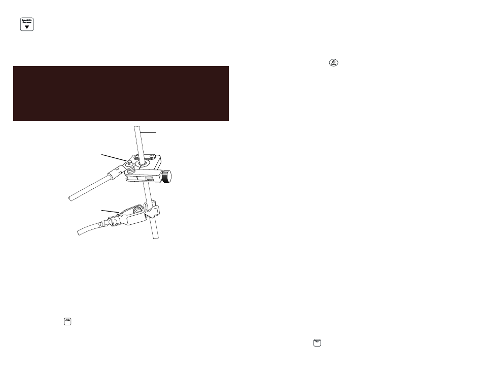
Fig. 3 - Piezoelectric sensor and ground clip on fuel line
Fuel injection line
Piezoelectric sensor
Ground clip
1- Clamp the piezoelectric sensor onto a clean unpainted section of any diesel injection
pipe. Do not over tighten the thumb screw (see Fig. 3)
2- Clip the alligator ground clip onto a clean unpainted section of the same injection
line.
3- Connect the forked terminal to the piezoelectric sensor.
4- Turn the instrument on.
5- If necessary change the number of cycles to match the engine under measurement
by pressing the (Number of cycles) button repeatedly until the display shows the
correct setting.
4- Start the diesel engine.
6- Read the RPM on the display.