Max. internal earth connection: 0.5 - 2.5-mm – Fire Fighting Enterprises Vibration Switch: Explosion Proof User Manual
Page 2
Doc. No. 0115-03
Page 2 of 4
30.01.06
All suitable for Zone 1 & Zone 2 use.
Ingress Protection Rating IP67 although any IP rating down to IP54 may be used if required, see Item. 8.6
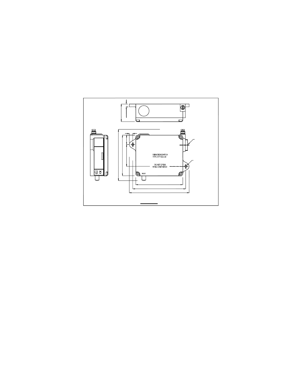
2. MOUNTING AND DIMENSIONS
The unit should be firmly mounted on a vertical face by M4 bolts, with the reset button at the bottom. See Fig. 1
for external dimensions and fixing centres.
The vibration switch will respond to vibrations in any axis (predominantly in a horizontal plane) and should be
fitted on the machine such as to ensure good transmission from likely sources of excess vibrations.
CABLE ENTRY
LEVEL
FIGURE 1
ENGLAND
2 POSNS.
FIXING HOLES
5.0 DIA.
M20 x 1.5 ISO
SET
41
m
m
6.
5m
m
8mm
22m
m
51
m
m
C
e
n
tre
s
95
m
m
1
20m
m
Ov
e
rall
110mm
124mm Centres
140mm Overall
PRINCIPLES OF OPERATION
The vibration switch is a simple mechanical device, operating by balancing magnetic attraction on a metal ball,
against acceleration forces produced by surrounding vibrations. The switch is mounted vertically with the ball
restrained in a conical seat by a permanent magnet. When the ball experiences sufficient acceleration,
(excessive vibration of the machine), it breaks free, falls and operates a Microswitch. The Microswitch provides
the electrical interface to cause machine shut – down.
Reset is by Push Button on the bottom of the switch. See Fig. 1
The operate point is controlled by the Set Level Screw on top of the switch. See Fig. 1
3. ELECTRICAL
CONNECTIONS
Contact Ratings: see Tables 1 & 2
Connections: see Fig 2
Connector core size: 0.5 - 2.5-mm
2
max.
Internal earth connection: 0.5 - 2.5-mm
2
max. (To match connector cable used)
External earth connection: 6.0 mm
2
max.
Approved cable glands must be used to suit cable and ensure acceptable IP requirements - See Item 8.6.
To ensure EMC requirements are met, it is recommended that SWA, MICC, Screened cable, or metal conduit
be used, with suitable earthing.