FEC AFC1200 User Manual
Page 7
)(& ,QF
8.3
Replacements
WARNING:
DO NOT CONNECT OR DISCONNECT CABLES OR OTHER SYSTEM
COMPONENTS WITH POWER APPLIED. FOLLOW LOCKOUT/TAGOUT AND
OTHER APPLICABLE SAFETY PRECAUTIONS WHEN CONNECTING OR
DISCONNECTING CABLING, WIRING, AND EQUIPMENT.
8.3.1 ISA Main Controller unit Replacement (No Partial Replacement)
The ISA Main Unit controls overall operations of the AFC1200 Fastening System. The values
for System configuration and operational programs/presets are stored on the components of
this System. Values are stored on a combination of EPROM, EEPROM, CMOS, and
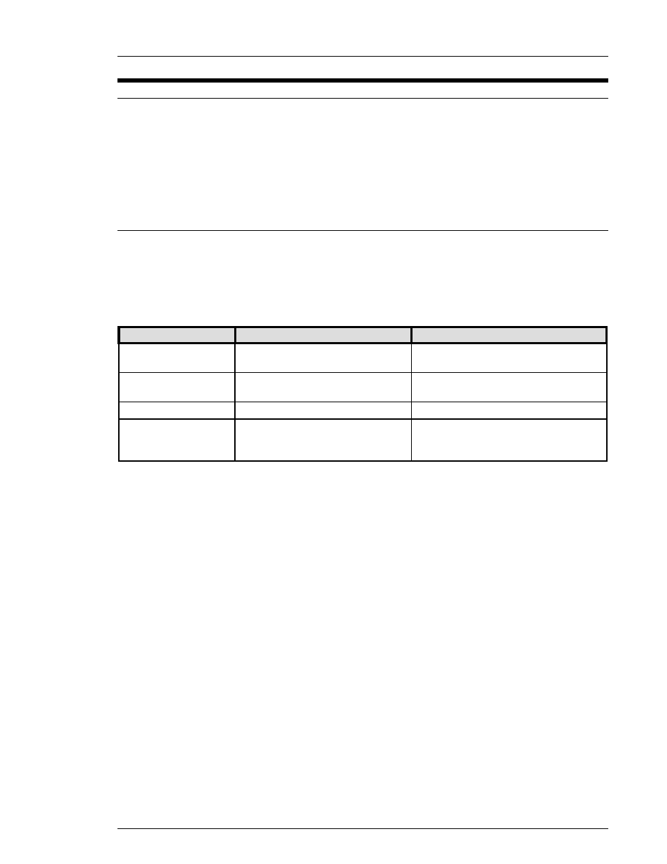
magnetic disk as indicated in the following chart:
PROCESSOR PCB / MAIN CHASSIS:
Hard Disk Drive (IDE Connector)
Floppy Disk Drive (FDD Connector)
Backup of preset configuration/
parameter values for fastening
operations
Magnetic Disk
PROCESSOR PCB
System configuration
CMOS
MULTI2 PCB
Preset configuration/parameter
values for fastening operations
EEPROM
PROCESSOR PCB/RDISK daughter
board, MULTI2 PCB
Operational Program
EPROM
Location
Function
Memory Device
The ISA Main Unit is not user-serviceable, and no attempt should be made to replace any
component of the Unit except for the Real Time Clock battery, as described in Section 8.3.2.
In the event of failure, the ISA Main Controller should be replaced as a complete assembly.
Do not remove the Controller cover (except as directed in Section 8.3.2) or attempt to repair
or modify the Unit. The circuit boards in the ISA Main Controller Unit should be handled by
FEC INC. personnel, only.
ISA Main Controller Units must be replaced with identical equipment. Ensure that the
hardware and software configuration of the replacement Unit is identical to that of the failed
Unit.
To replace the ISA Main Controller, proceed as follows:
1. Ensure that there is no power to the System, then disconnect all power cables and
communication cables connected to the ISA Main Unit.
2. Carefully remove the Main Unit from the enclosure. (Sections 4.2.2 and 4.3)
3. Verify that the replacement Unit's hardware and software configuration is identical to the
configuration of the failed Unit. Secure the replacement Unit in the enclosure.
4. Verify that the power source is within specifications (Section 2.3), then connect all power
cables and communication cables to the replacement ISA Main Unit.
5. Prepare the System for operation by following the procedures in Chapter 5.
Chapter 8: Maintenance and Inspection
Page 8-7