FEC AFC1200 User Manual
Page 5
)(& ,QF
8.2.3 Nutrunner (Tool) Motor
WARNING:
Follow Lockout/Tagout and other safety precautions when connecting or
disconnecting cabling, wiring, and equipment.
When performing the following inspections, verify that the System is disabled
prior to touching any moveable components.
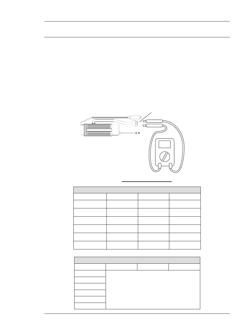
1. Disconnect the motor homerun cable from the tool motor connector (FIG. 8-2-3).
2. Measure the resistance between windings. Refer to FIG. 8-2-3 and the chart, below.
3. Measure the insulation resistance between each pair and the frame.
Insulation resistance: Using a megohmmeter, 500 VDC, 50 megohms or more, test the
insulation resistance between the motor windings and the motor case. The values should
register more than 50 megohms for each winding. Refer to the Insulation Resistance chart.
TOOL
MEGOHMMETER
TOOL MOTOR CONNECTOR
FIG. 8-2-3 motor inspection
.7Ω
.7Ω
.7Ω
400W (M4)
4.0Ω
4.0Ω
4.0Ω
200W (W3)
2.1Ω
2.1Ω
2.1Ω
200W (M3)
4.4Ω
4.4Ω
4.4Ω
100W (M2)
15.3Ω
15.3Ω
15.3Ω
70W (W1)
12.8Ω
12.8Ω
12.8Ω
60W (M1)
B - C
A - C
A - B
MOTOR SIZE
Motor Winding Resistance*
Rev. 1/08/01
400W (M4)
200W (W3)
200W (M3)
100W (M2)
70W (W1)
More than 50 megohms at 500 VDC
60W (M1)
C - D
B - D
A - D
MOTOR SIZE
INSULATION Resistance
Chapter 8: Maintenance and Inspection
Page 8-5