Appendix: technical specifications, Inputs ratings – E-Mon E-PS-S-HV-RTU User Manual
Page 33
Appendix: Technical Specifications
27
Appendix: Technical Specifications
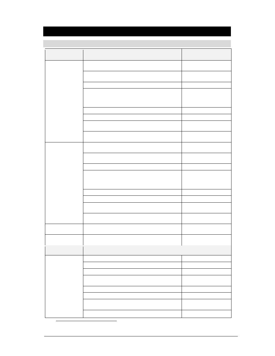
Inputs Ratings
AC Voltage
inputs
Va, Vb, Vc and Vref - 50/60Hz
High input
impedance = 10MΩ
Ω
Ω
Ω
Voltage rating:
120 up to 277 Volts (L-N), 207 to 480 Volts (L-L)
Voltage range
Crest factor >2 [V
L-N
x 1.2 x 2]
0 -332 V r.m.s,
peak up 665V (for PQ)
Maximum Line to Line voltage
1152 V r.m.s
Temporary over voltage between live conductors and
earth
Transient over voltage between live conductors and
earth (TRM optional module, from 15 µs up to ms)
1500 V r.m.s
6 kV peak, 2kV
measurement
Starting voltage
0.1%U
n
Burden per phase
< 0.5 VA
Overload withstand for 1 minute phase-to-ground
(ANSI C12.1 & IEC 62053-22, protective class II)
4000V r.m.s
Reference voltage
U
n
120V up to 277V
L-N (direct)
standard
Rated impulse voltage
(ANSI C12.1 & IEC 62052-11, protective class II)
6000V peak
Voltage rating:
57.73 up to 120 Volts (L-N), 100 to 207 Volts (L-L)
Voltage range
Crest factor >2 [V
L-N
x 1.2 x 2]
0 -144 V r.m.s,
peak up 288V (for PQ)
Maximum Line to Line voltage
500 V r.m.s
Temporary over voltage between live conductors and
earth
Transient over voltage between live conductors and
earth (TRM optional module, from 15 µs up to ms)
240 V r.m.s
1.5 kV peak
Starting voltage
1
0.1%U
n
Burden per phase
< 0.2 VA
Overload withstand for 1 minute phase-to-ground
(ANSI C12.1 & IEC 62053-22, protective class II)
4000V r.m.s
Reference voltage
U
n
57.73V up to
120V L-N (via PT)
optional
Rated impulse voltage
(ANSI C12.1 & IEC 62052-11, protective class II)
6000V peak
Voltage/Current
inputs
Terminals for wires size
Blades (Socket meter
standard – C12.10)
Ground input
Terminals for wires size
According to Socket meter
standard – C12.10
AC Current inputs 3 (4 optional) Galvanic isolated Inputs
Current class Imax
10A & 20A
Maximum measurable short circuit current (Isc)
10 x I
n
Burden per phase (In = 5 A)
< 0.2 VA
Starting current (I1, I2, I3) – average
Starting current (I1, I2, I3) – real time
0.2% I
n
1.0% I
n
Over current withstand for 1 s non-recurring
50 x I
n
Isolation
4000V r.m.s
Terminals for wires size
Blades (Socket meter
standard – C12.10)
Reference Current
Basic model In = 5
A
(TA = 2.5A)
3 (4 optional) Galvanic isolated Inputs
FORM 9 (39 optional)
1
Starting voltage, interruptions and dips measurement applicable only with installed APS