Ubg-16 wiring diagram – Electronics International UBG-16 User Manual
Page 23
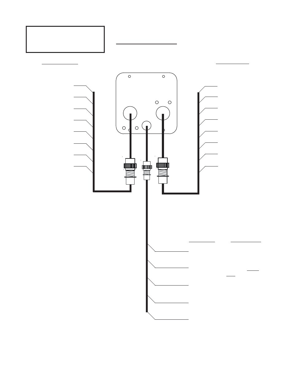
UBG-16
Wiring Diagram
UBG-16
Back View
1
2
3
4
5
6
7
8
1
2
3
4
5
6
7
8
Right Extension Cable Harness.
Left Extension Cable Harness.
19
Channel #1.
Channel #2.
Channel #3.
Channel #4.
Channel #5,
Channel #6.
Channel #7.
Channel #8.
Channel #1.
Channel #2.
Channel #3.
Channel #4.
Channel #5,
Channel #6.
Channel #7.
Channel #8.
Right Channels
For monitoring CHT's and other
temperatures or functions.
Left Channels
For monitoring EGT's and other
temperatures or functions.
Note: Any channel used to measure a temperature must
be connected to a Type K thermocouple extension cable.
Note: The first 4 or 6 channels on the left and right must
be used to monitor EGT and CHT respectively.
Note: If using the 7th column of bars to display TIT or
Oil Temp, the probe must be connected to the next LEFT
channel after the last EGT channel.
Note: OAT or Carb Temp must be connected to channel
7 or 8 on the left or right. These are "precision" chan-
nels.
Note: Any left or right channel will accept any one of
E.I.'s probes or Functional Modules.
Note: Varying cable lengths will not affect accuracy.
Display Dimming.
Power Lead.
Ground Lead.
CP-1 Intensity
Control Pot.
12/24 Volt, Radio
Bus. via 5 amp fuse.
Ground
Description Connects To:
White/Orange
Red
Black
White/Grn
White/Yel
Connecting Wire Harness.
(Optional) External Warning Control
Line. Can be connected to a relay to
control an external light, buzzer, etc.
This line grounds when a warning is
blinking on the display. Current must
be limited to 1/10 amp maximum.
(Optional) RS232 Data Output Line.
Connect to MUX-8 to record data.
WARNING
WARNING
WARNING
WARNING
WARNING
Do Not use screws that penetrate
the instrument face more than
.125". Display damage may result.
Rev. A 12/29/04