Plug-in module typical systems, P s - 5 2 x x - x x x - x x x - x, Sinking or sourcing – Electro Cam PL-1746 User Manual
Page 4
Component(s)
Qty.
Part Number
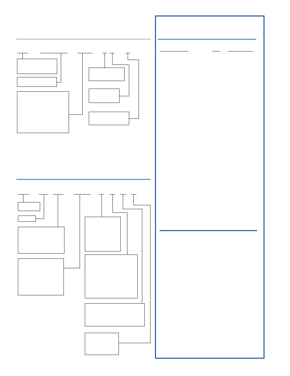
PL-1746-C01 System
C01 Plug-In Module
(1)
PL-1746-C01-R1
Resolver
(1)
PS-5275-11-ADR
Resolver Cable
(1)
PS-5300-01-010
Keypad/Display
(1)
PS-6400-24-001
Keypad-to-controller cable(s)
(1)
PS-6300-01-005
I/O Rack
(1)
PS-PS-4108-13-L08
I/O Rack Cable
(1)
PS-4308-10-005
SLIMLINE™ Output Modules
(16)
EC-ODC060-3
SLIMLINE™ Analog Modules
(2)
EC-SANL-010V
PL-1746-C02 System (C03 for
†
Sinking)
C02/C03 Plug-In Module
(1)
PL-1746-C02-R1
Resolver
(1)
PS-5275-11-ADR
Resolver Cable
(1)
PS-5300-01-010
Keypad/Display
(1)
PS-6400-24-001
Keypad-to-controller cable(s)
(1)
PS-6300-01-005
PL-1746-C04 System
C04 Plug-In Module
(1)
PL-1746-C04-R1
Resolver
(1)
PS-5275-11-ADR
Resolver Cable
(1)
PS-5300-01-010
Keypad/Display
(1)
PS-6400-24-001
Keypad-to-controller cable(s)
(1)
PS-6300-01-005
Plug-In Module
Part Number Breakdown
Resolver
Part Number Breakdown
4
P L - X X X X - XXX - X X - X
SUB-CATEGORY
C01 = Display, 32 Real World I/O with
External I/O racks
C02 = Display, Built-in 8 Inputs and 6
Sourcing
†
DC Outputs, 1.5 A
C03 = Same as C02, except with
Sinking
†
outputs
C04 = No Display, No Real World I/O
PL =
Plugs into backplane
Utilizes Allen-Bradley
technology.
OPTIONS
S = Shift Register & Output
assignment feature
NUMBER OF
TRANSDUCERS
1 = One
TYPE TRANSDUCER
R - Resolver
E - Encoder
PLATFORM TYPE
1746 = SLC 500
P S - 5 2 X X - X X X - X X X - X
HOUSING
A - Can housing w/flange
or foot endbells.
C - Stainless steel
square housing.
E - 74 mm bolt spacing,
flange mount
S - Servo mount
(.12 = size 11;
.38 = size 25 )
LOCATION OF CABLE CONNECTION
W - With stripped & tinned leads
G - Right (120
°
from top on “A” housings)
R - Rear (not available on Geared Resolver)
L - Left (120
°
from top on “A” housings)
S - Side (Top)
TYPE OF CABLE CONNECTION
D - Military bayonet style connector
T - Terminal strip with NO conduit
entrance
V - No connector, just stripped &
tinned wires
S - Sealed connector — screw type
Note:
Part # PS-5903-01-001
conduit entrance for
terminal strip models
sold separately.
OPTION
V - Vertical Mount
Note: Only required
for vertical mounting
of PS-5262-11-CTX
Models.
RATIO
11 - Standard 1:1 (Note: 3rd digit
not used on Standard 1:1)
021 - Geared 2:1 - Ext. shaft to
internal resolver shaft
thru
361 - Geared 36:1 - Ext. shaft to
internal resolver shaft
Various ratios available,
contact Factory.
Resolver
PL
µ
S
Part Number
SHAFT SIZE
12 -
1/8 DIA.
15 -
15 mm DIA.
20 -
20 mm DIA.
38 -
3/8” DIA., 2.06” Bolt Flange
62 -
5/8” DIA., 2.25” Bolt Flange
75 -
3/4” DIA.
Plug-In Module
Typical Systems
†
SINKING or SOURCING
( as pertaining to Electro Cam Corp. products )
Sinking means that when the logic is true and the output (or
input device) is ON, the output (or input device) is providing a
DC common or ground to the connected device.
Sourcing means that when the logic is true and the output
(or input device) is ON, the output (or input device) is provid-
ing a +DC voltage to the connected device.
This information is important when interfacing an Electro Cam
Corp. product with another electronic device. If you are using
an Electro Cam Corp. product input to an Allen-Bradley 1746-
IN16 “sinking” input card* or similar A-B device, you have to
supply a +DC voltage (Electro Cam Corp.
Sourcing output)
to this card, NOT a DC common or ground. In these cases,
Sinking is what the card does with the input voltage; sinks it
to common or ground.
* Other manufacturers include, but not limited to: Koyo (for-
merly GE Series 1, Texas Instruments, or Siemens SIMATIC
PLS’s) that use descriptions similar to Allen-Bradley.