Teledyne 300P - Percent oxygen analyzer User Manual
Page 7
2-1
Teledyne Analytical Instruments
Percent Oxygen Transmitter
Operational Theory 2
Operational Theory
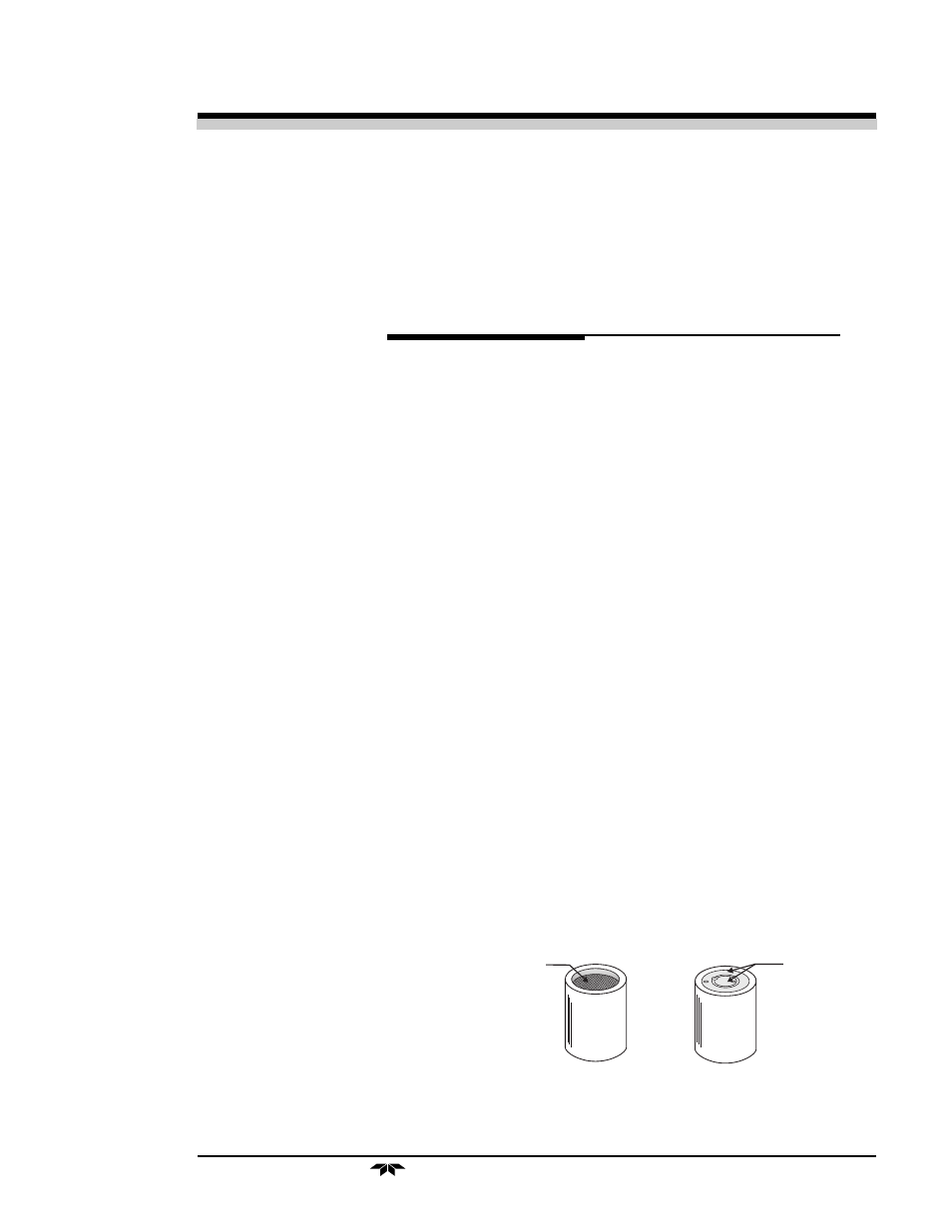
Top View
Bottom View
Concentric Foil
Contact Rings
Screen
Figure 2-1: Micro-Fuel Cell
2.1 Transmitter Description
The transmitter consists of an RFI proof enclosure which contains the
O
2
Sensor Assembly, 2-Wire Transmitter Circuitry and RFI Filters.
Mounted on the left side is a junction box which contains a three conductor
terminal strip for all external electrical connections. The bottom of the box
contains two bulkhead fittings for the 1/8" tubing used for bringing the
sample into and out of the sensor assembly. The transmitter assembly
contains four holes in the mounting flange for vertical surface mounting.
Access to the junction box is obtained by the removal of two screws
followed by the removal of the cover. Access to the O
2
sensor and PC
board is through an RFI gasketed door held shut by 4 screw clamps.
2.2 Sensor Description
The Micro-Fuel Cell is a sealed plastic disposable oxygen transducer
that measures 1¼ inches in diameter and is ¾ inch thick (see Figure 2-1).
Inside of the cell are a cathode and anode immersed in 15% aqueous KOH
electrolyte. At one end of the sensor is a Teflon diffusion membrane; the
other end is sealed with a polyethylene membrane. At the rear of the cell is
a contact plate consisting of
two concentric foils. The
foils mate with spring-
loaded contacts in the sensor
block assembly and provide
the electrical connection to
the rest of the analyzer.
The sensing cathode,
located beneath the diffu-