Installation and operation – Fulton Ancillary Equipment Horizontal and Vertical Return Systems User Manual
Page 12
10
RTN IOM
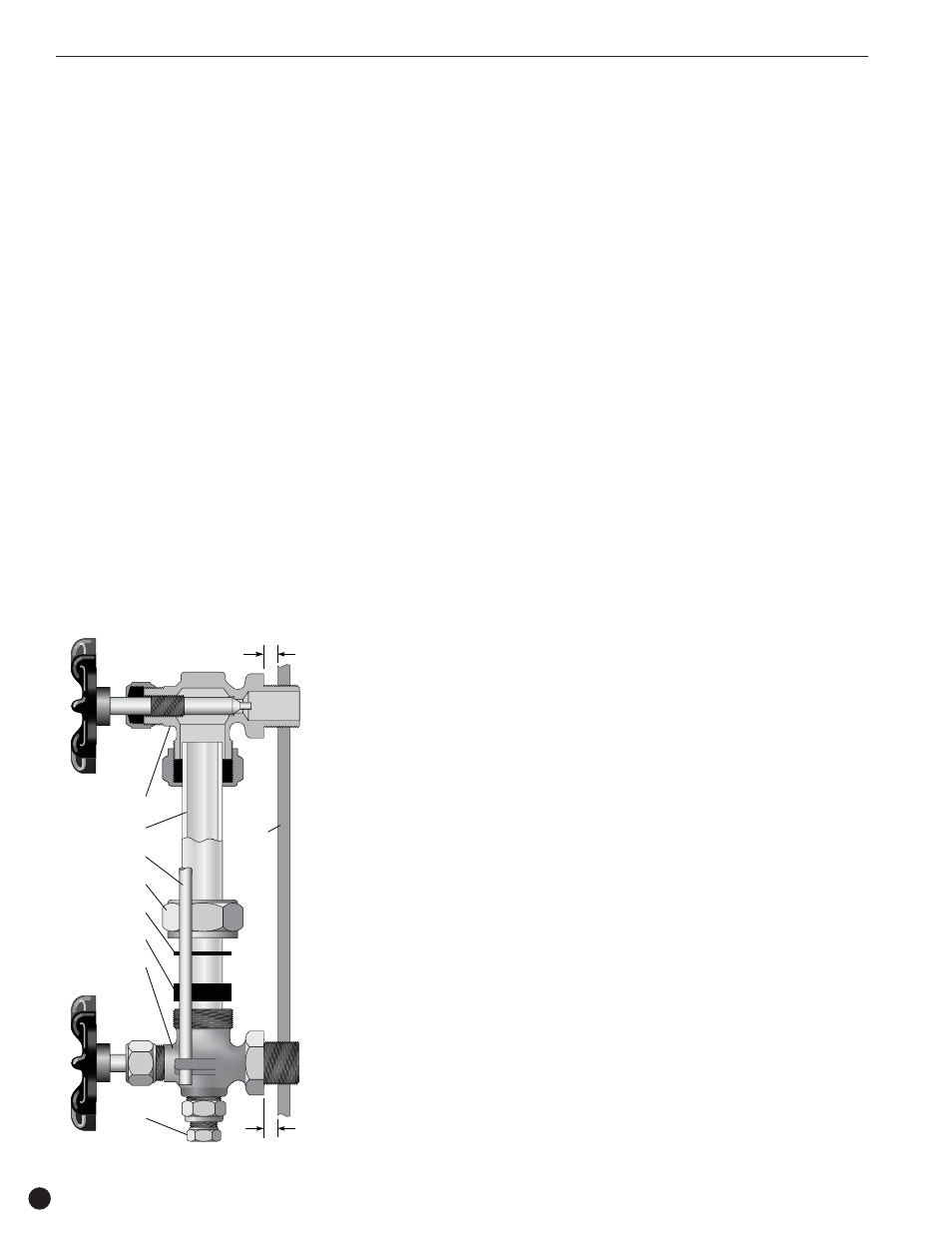
Water Gauge & Gauge
Glass Installation
Instructions
NOTE
Only properly trained personnel should
install and maintain water gauge glass and
connections. Wear safety glasses during
installation. Before installing, make sure
all parts are free of chips and debris. Keep
gauge glass in original packaging until
ready to install.
1. Verify the proper gauge has been
supplied.
2. Examine the gauge glass and packings
carefully for damage before installation.
Do not use the glass if it contains any
scratches, chips or any other visible
signs of damage.
3. Do not subject the gauge glass to
bending or torsional stresses.
4. Apply Teflon tape or pipe dope to pipe
threads. Install top gauge fitting (fitting
without a drain valve) into the uppermost
tapping. Wrench tighten the fitting until is
is snug and the glass outlet is pointing at
five o’clock (about
1
/
8
turn from its final
downward vertical position).
5. Install the bottom gauge fitting (the fitting
with a drain valve) until it is snug and the
glass outlet is pointing directly upward.
Verify top and bottom fittings are
threaded into the tappings the same
number of turns (distance A - distance B).
6. Remove glass packing nut, friction
washer and glass packing from the
fittings, and replace them in the same
order on both ends of the gauge glass.
Push both packings about an inch up
the gauge glass.
7. Gently insert one end of the glass into
thetop gauge fitting. Keeping the glass
inside the top fitting, gently rotate the top
gauge fitting clockwise until vertically
aligned with the bottom gauge fitting,
then insert glass into bottom fitting until
glass bottoms out on the the shoulder
inside the bottom fitting.
8. Carefully raise glass about
1
/
16
” and
slide lower glass packing down until the
glass packing contacts the lower gauge
fitting. Do Not allow the glass to remain
in contact with any metal.
9. Carefully slide upper glass packing up
as far as possible.
10.Hand tighten both glass packing nuts,
then tighten
1
/
2
turn more by wrench.
Tighten only enough to prevent leakage.
Do not over tighten! If any leakage
should occur, tighten slightly, a quarter
turn at a time, checking for leakage after
each turn.
WARNING
Improper installation or maintenance of
gauge glass and connections can cause
immediate or delayed breakage resulting
in bodily injury and/or property damage.
Float Valve Assembly
Instructions for Vertical
Return System
(Figure 4)
1. Remove top plate and gasket.
2. Apply Teflon tape or pipe dope to all pipe
threads. Assemble rod to float and valve.
3. Screw float assembly into the cold water
supply fitting welded in the tank.
4. Adjust float valve with the ball position
lock. (Water level should be approximately
1” from the top of sight glass.)
5. Replace top plate and gasket.
Float Valve Assembly
Instructions for Horizontal
Return System
(Figure 5)
a. Remove end plate and gasket.
b. Apply Teflon tape or pipe dope to all pipe
threads. Assembly rod to float and
valve.
c. Screw float assembly into the cold water
supply fitting welded in the end plate.
d. Adjust float valve with the ball position
lock (water level should be approximately
1” from top of sight glass).
e. Insert into tank, replace gasket and bolt
end plate into place.
WARNING
Incoming water pressure to float valve
cannot exceed 40 PSIG. Use PRV if
pressure is above 40 PSIG.
NOTE
If a Square D float switch is installed in
lieu of the float valve assembly shown in
firgure 4, then refer to the cut sheets for
any adjustments and/or maintenance.
Installation and Operation
A
B
Top Gauge
Fitting
Gauge Glass
Guard Rod
Vessel
Wall
Drain
Valve
Glass Packing Nut
Friction Washer
Glass Packing
Bottom Gauge
Fitting
Figure 3