Installation and operation, Installation location, Rigging – Fulton Ancillary Equipment Horizontal and Vertical Return Systems User Manual
Page 11: Piping
RTN IOM
9
Installation Location
The condensate return system should be
located to permit access to operating controls,
instruments and inspection openings.
The foundation should be level and
designed to support the load. Calculations
should be based upon the maximum or
filled weight of the system.
Rigging
Qualified riggers should be used to place
the system on the foundation. All rigging
equipment must be carefully placed to
avoid damaging or loosening piping,
nozzles and other parts of the assembly.
The system should be securely bolted to
the foundation.
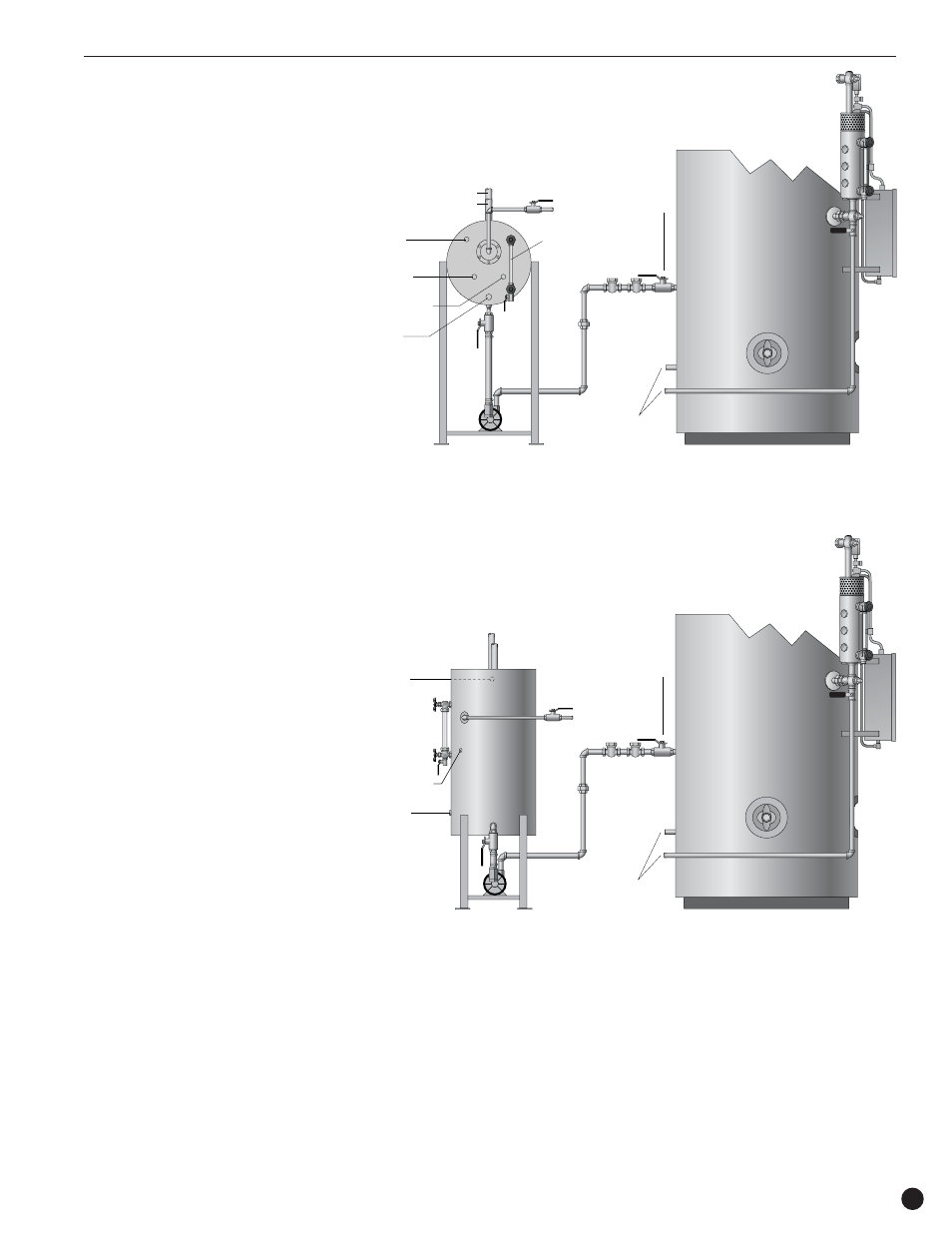
Piping
(Figures 1 and 2)
1. Prior to piping, all foreign material or
debris must be removed to prevent
possible malfunctions. Clean tank by
flushing with hose.
2. Avoid imposing any piping strain on the
pump(s). Provide expansion joints and
independently supported pipe hangers
where necessary.
3. Isolating valves are installed to allow for
cleaning or repairs.
4. Make-up water and pump discharge
piping must be sized in accordance with
any applicable local or state codes.
Sizing should be determined by flows,
pressures, and distances, not pump size.
5. Install a stop valve and two check valves
in the pump discharge line.
6. Vent piping should be vertical, full size,
free of valves, bends or restrictions and
piped to a safe location.
7. Over flow piping should be full size, free of
obstructions and piped to a safe location.
Installation and Operation
Condensate
Return Tank
Cold
Water
Supply
Thermometer
*
Steam
Injector
*
Electric
Control
Panel
Water Column
and Sight Glass
Shut Off
Valve
To Blowdown
Separator
Overflow
Opening
Sight
Glass
Union
Check
Valves
Vent
Pump/
Strainer
Return
*
Supplied with optional preheat kit assembly
(NOTE: Aquastat opening is the same dimension off centerline of sightglass but on opposite side)
Oil, Gas or
Electric Boiler
Aquastat
*
Figure 1
Condensate
Return Tank
Cold
Water
Supply
Thermometer
*
Aquastat
*
Steam
Injector
*
Electric
Control
Panel
Water Column
and Sight Glass
Shut Off
Valve
To Blowdown
Separator
Overflow
Opening
Sight
Glass
Union
Check
Valves
Vent
Pump/
Strainer
Return
*
Supplied with optional preheat kit assembly
(NOTE: Aquastat opening is the same dimension off centerline of sightglass but on opposite side)
Oil, Gas or
Electric Boiler
Figure 2