Installation details-automatic powerstop, Concrete dock face, Low pit floor – Poweramp POWERSTOP 4.2009 User Manual
Page 9: Driveway mount, Cantilevered dock
7
4111-0014 — November 2006
Sept.2007
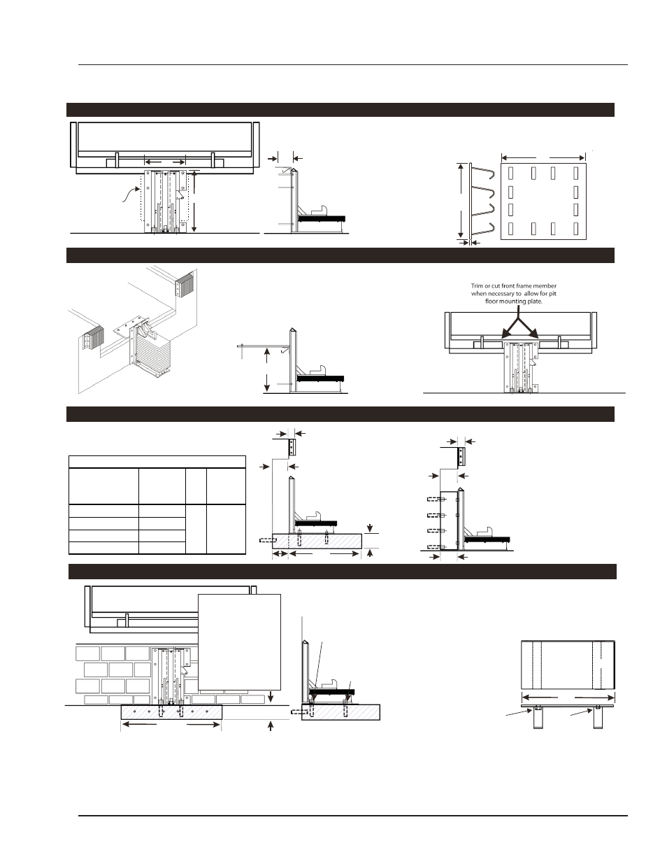
INSTALLATION DETAILS-AUTOMATIC POWERSTOP
A
ti
i
d
t i
t
i i
ff
t t S
t
I
W
th
i ht t
k
d
t h
ith
t
i
ti
Concrete Dock Face
(Standard installation)
Low Pit Floor
(Distance from pit floor to drive under 24”)
Driveway Mount
(Recommended when dock face is unsuitable for PowerStop Mounting)
Cantilevered Dock
(For bumper projection >4” or cantilevered dock or Edge-of-Dock leveler)
48”
8” Min.
Driveway mount requires
attachment to a concrete
drive greater than 8”
thick. For asphalt drive,
pour 48”x48”x8” (min.)
concrete pad and include
six (6) 3/4” dowels into
foundation wall. Then
proceed with adhesive
anchors or weld plate
embed.
Anchor pit floor mounting plate (minimum 3/8” x 20”W x 8” D)
(Part #9414-0056) with four (4) (3/4”x 5 1/4” min.) wedge anchors.
Weld mounting plate to curb steel and back plate of PowerStop with
a continuous 1/4” fillet weld. Anchor back plate of PowerStop to
dock face with a minimum or (4) 3/4” x 5 1/4” wedge anchors
(Kit#2103-0003).
Determine offset
then proceed with
“Driveway Mount”
instructions below.
20”
20”
Weld three sides of PowerStop back plate to the optional
embed mounting plate (Part #7953-0119) with ten (10)
4” long 1/4” fillet welds.
5 1/4” minimum
27”
To determine size offset required, take total effective
bumper projection (bumper size plus any cantilever) and
subtract 4”.
48”
8” Min.
Using back plate as a guide, drill six (6) holes for
wedge anchors (3/4”x 5 1/4” min.) (Kit #2103-0003)
(Kit #9414-0058)
Install two (2) 1” Dia. adhesive
anchors into 1-1/8” Dia. x 7”
deep hole at rear of PowerStop.
Install two (2) 3/4”
Dia. x 5 1/4” min.
wedge anchor at
front of PowerStop.
Adhesive Anchors Method
Drive Embed Method
Wedge Anchors Method
Wall Embed Method
27”
14”
Weld method
Properly locate and level the drive embed weld plate (Part#7953-
0059) in the drive approach. Observe Cantilever conditions for
proper positioning. Weld restraint to embed plate with a
continuous ¼” filet weld.
Bolt on Method
Properly locate and level the
drive embed plate
(Part#9414-0057) in the drive
approach. Observe cantilever
conditions for proper positioning.
Using the bolts included, bolt
the restraint to the embed plate.
If <24”
18”
Optional
Embed
Plate
3/8”
(Front)
3/4” Dia. X 6” min.
bolt
(Rear)
1” Dia. X 6” min.
bolt
Driveway Mount
Wall Mount
Dim. B
Dim. A
Offset Formula
Dim. A
Dim. B
Offset
Bumper Projection
Cantelever
4"
+ Dim B
6"
+ Dim B
-4" = Offset
10"
+ Dim B
15"
+ Dim B
For filler requirements from 1 ½”to 7
½” use cantilever bracket #9414-0052
weld to embedded
mounting plate (Part #7953-0119)
For filler requirements for 8 3/4” to 13
3/4” use cantilever bracket #9414-
0053 and anchor cantilever bracket to
the dock face (3/4” Dia. X 5 1/4” min.)
(Kit #2103-0004) or weld to
embedded mounting plate
(Part #9414-0052).
and anchor cantilever bracket to the
dock face or
Dim. B
Dim. A
Offset
Dim. B