Installation – Poweramp CM SERIES MECHANICAL User Manual
Page 16
14
4111-0006 — Sept 2010
Sept 2012
INSTALLATION
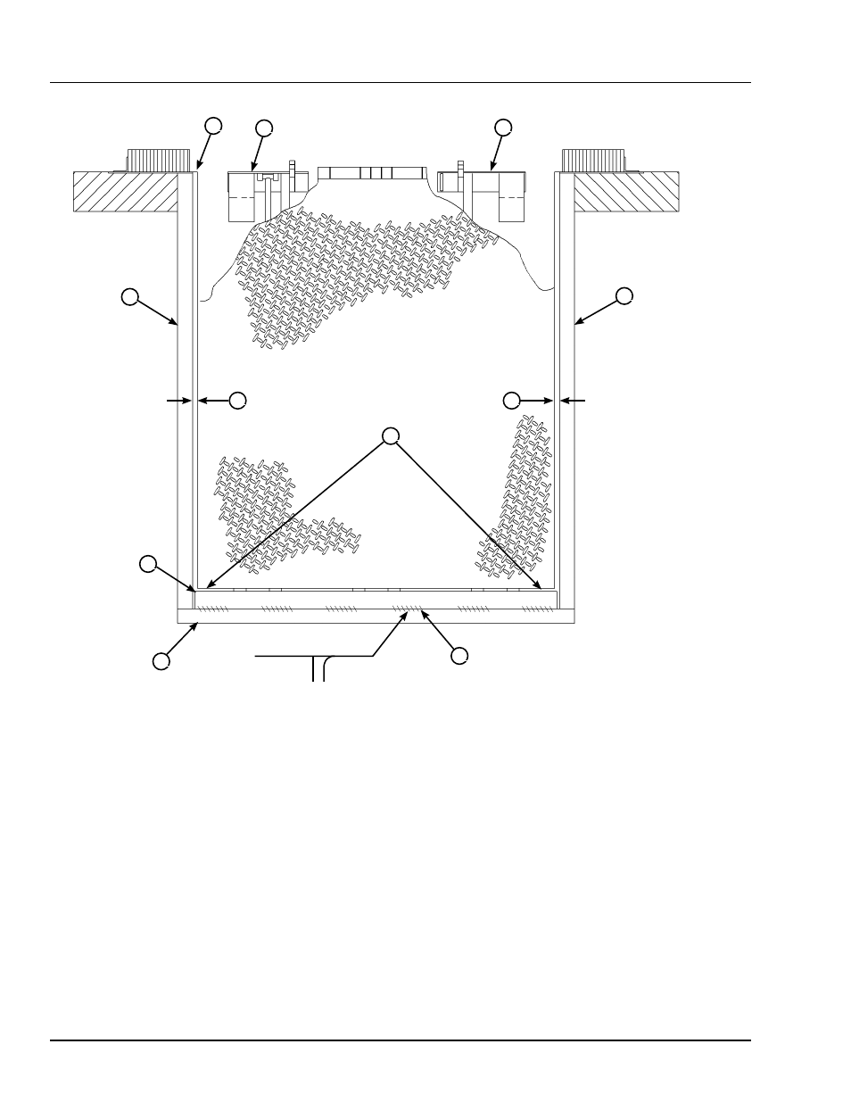
A— Front of Dock Pit
B— Dock Leveler Frame
C— Side Pit Curb Angle
D— Gap [3/4 in. (19 mm)
Minimum]
E— Pry Locations
F— Rear Hinge Frame
Angle
G— Rear Pit Curb Angle
H— Flare Bevel Weld, Typical
(To Fit Spacing)
8. With rear hinge frame angle (F) tight against rear
pit curb angle (G), perform/check the following:
• Pry between the platform and rear hinge frame
angle at locations (E) to make sure rear edge of
platform is parallel to the rear hinge frame angle
(F).
• Gap (D) must exist equally along both sides of
leveler so weather seal (if equipped) will not bind
during dock leveler operation.
9. If gap (D) cannot be obtained equally at both sides
of leveler, grind or add material at the rear edge of
rear hinge frame angle (F) as needed.
10. Allow the dock leveler to rest fully on the shim
stacks. Make sure the leveler is in the cross-traffic
(stored) position with lip resting on lip keepers.
11. Check that a smooth and level transition exists
between the dock floor and the dock leveler
platform. Add or remove shims as necessary until
a smooth transition is obtained.
12. If leveler cannot be squared and made level
as instructed in steps 8 – 10, contact Poweramp
Technical Services.
G
H
A
B
B
E
C
F
C
6 in.
(152 mm)
3/8 in.
(9.5 mm)
D
D