27 ide connectors, Floppy connector, Chapter 2: installation – American Megatrends X6DVA-EG User Manual
Page 47: Ide 1 ide 2 floppy
Chapter 2: Installation
2-27
IDE Connectors
T h e r e a r e n o j u m p e r s t o
configure the onboard IDE#1
and #2 connectors (at J44
and J38, respectively). See
the table on the right for pin
definitions.
Pin Number
Function
1
Reset IDE
3
Host Data 7
5
Host Data 6
7
Host Data 5
9
Host Data 4
11
Host Data 3
13
Host Data 2
15
Host Data 1
17
Host Data 0
19
GND
21
DRQ3
23
I/O W rite-
25
I/O Read-
27
IOCHRDY
29
DACK3-
31
IRQ14
33
Addr 1
35
Addr 0
37
Chip Select 0
39
Activity
Pin Number
Function
2
GND
4
Host Data 8
6
Host Data 9
8
Host Data 10
10
Host Data 11
12
Host Data 12
14
Host Data 13
16
Host Data 14
18
Host Data 15
20
Key
22
GND
24
GND
26
GND
28
BALE
30
GND
32
IOCS16-
34
GND
36
Addr 2
38
Chip Select 1-
40
GND
IDE Connector Pin Definitions
(J44, J38)
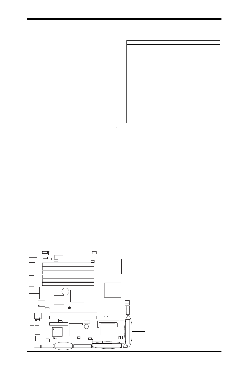
Floppy Connector
The floppy connector is located
on J24. See the table below for
pin definitions.
Pin Number
Function
1
GND
3
GND
5
Key
7
GND
9
GND
11
GND
13
GND
15
GND
17
GND
19
GND
21
GND
23
GND
25
GND
27
GND
29
GND
31
GND
33
GND
Pin Number
Function
2
FDHDIN
4
Reserved
6
FDEDIN
8
Index-
10
Motor Enable
12
Drive Select B-
14
Drive Select A-
16
Motor Enable
18
DIR-
20
STEP-
22
W rite Data-
24
W rite Gate-
26
Track 00-
28
W rite Protect-
30
Read Data-
32
Side 1 Select-
34
Diskette
Floppy Connector Pin Definitions (J24)
GLAN1
®
S
UPER X6DVA-4G
GLAN2
DIMM 2B
DIMM 2A
DIMM 3B
DIMM 3A
DIMM 1A
DIMM 1B
8-pin
PWR2
SMB
PWR
FP
C
TR
L
Speaker
WOR
GLAN
CTLR
X4 PCI-Epxess
PCIX #6 (PCIX-133)
North
Bridge
VGA
COM1
USB0/1
KB/
Mouse
PW4
ATX
PWR1
24-Pin
Fan1
PW1
CPU 1
CPU 2
COM2
6300ESB
ICH
GLAN
CTLR
PWR
Fault
J2
J3
J4
J1
PW3
J18
J19
J20
J21
J22
J23
J8B1
JPL1
LAN1Enable
JPL2
LAN2Enable
PCIX #5 (PCIX-100)
JPR1
Alarm
Reset
J9B1
J15
J13
JPA1(*SCSI Enable)
PCIX slots/
SMB Connect
JF2
PWLED/
SPKR
PCI-E#4
J14
Battery
Fan6 Fan5
JPG1
J17
VGA Enable
32- bit PCI #1
J5
Printer
J10
Floppy
J24
SCSI
J28
JL1
IDE 2
J38
Fan4
SATA0
SATA1
JS0
Cha. Intru
JS1
J
B
T
1
Clr CMOS
J41
IPMI
JWD
WD
IDE 1
J44
JF1
Fan3
E7320
(Lindenhurst
-VS)
MCH
PXH
(PCI-E/
PCIX
Interface)
SI/O
VGA
CTLR
SCSI (LSI
53C20)
64- bit
64- bit
USB2,3
JA1
JSLED
SATA
LED
D
S
9
Fan2
PW2
JWOL
D
S
7
D
S
8
P
O
S
T
L
E
D
System LED
SCSI
ChannelTerm.
Enable
JPF PWR Force On
BIOS
DS1
DS4
DS2
DS3
CPU
PW LED
CPU1 VRM
OHLED
CPU2 VRM
OH LED
DS5
PWR LED
WOL
SCSI LED
IDE 1
IDE 2
Floppy