Set output facility code – Pach and Company AWRR User Manual
Page 2
Step 1
Set JP1 to 5VDC if the AWRR is connected to the AeGIS 9000 Series (see fig. 1). If the AWRR purchased as a package
with the AeGIS 9000 Series, the systems are prewired from the manufacturer.
Step 2
Turn the power OFF on the AeGIS 9000 Series.
Step 3
Connect the wires as shown on fig.1.
Step 4
Turn the AeGIS 9000 power ON.
Step 5
The Red LED will turn ON then the Green LED will flicker and the Red LED will turn OFF.
Step 6
Install the antenna on top of the AeGIS 9000 Series.
SET OUTPUT FACILITY CODE
Step 1
Set the WIEGAND OUPUT FORMAT to 26-BIT (see figure 1 to locate the DIP SWITCH (A), switch #1).
Step 2
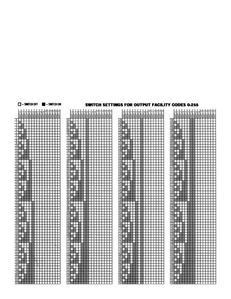
Set the OUTPUT FACILITY CODE (see fig. 1 DIP SWITCH (C) is labeled OUTPUT (0-7)). See table below to set the facility
code. Warning: Do not follow the number labeled on the DIP SWITCH.