Nova-Tech LMI Roytronic Excel Series AD Metering Pump User Manual
Page 14
14
INSTALLATION
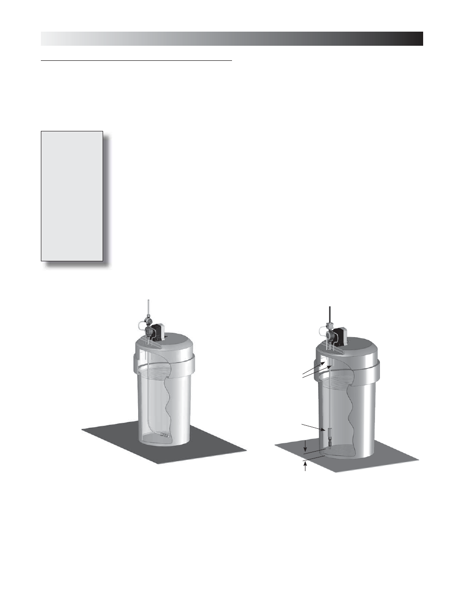
Use Ceramic
Weight
2.0 in. (50 mm)
for Sediment Accumulation
Foot Valve
Tilted Sideways WILL NOT PRIME
INCORRECT
Foot Valve Must
Remain Vertical
CORRECT
3.8 Foot
Valve/Suction
Tubing
Installation
The Foot Valve acts as a check valve to keep the pump primed in suction lift applications.
The foot valve is designed to be submersed in the solution tank or drum and must sit in
a vertical position at the bottom. Position approximately 2 inches (50 mm) off the bottom
if the tank or drum contains sediment.
The ceramic weight, when installed, helps position the foot valve in a vertical position.
1. Attach the foot valve to one end of the suction tubing (see Tubing Connections, Sec-
tion 3.3).
2. Slide the ceramic weight over the tubing end until it contacts the top of the foot valve
coupling nut.
3. Place foot valve and tubing into the solution tank. Check that the foot valve is vertical
and approximately 2 inches (50 mm) from the bottom of the tank or drum (see illus-
tration). Connect the other end of the tubing to the suction side of the pump head
(bottom side) (see Tubing Connections, Section 3.3).
Pump models
equipped with
high-viscosity
liquid ends are
not equipped
with foot valves.
Flooded suction
is recommended.
A 1/2" NPT
connector is
included for
flooded suction
installations.
Return Lines
Must Not Be
Submerged