5 motherboard overview, 1 motherboard layout, 6 chapter 1: product introduction – Asus P4BP-MX User Manual
Page 16: Super i/o, Pci1, Pci2 pci3, Socket 478
1-6
Chapter 1: Product introduction
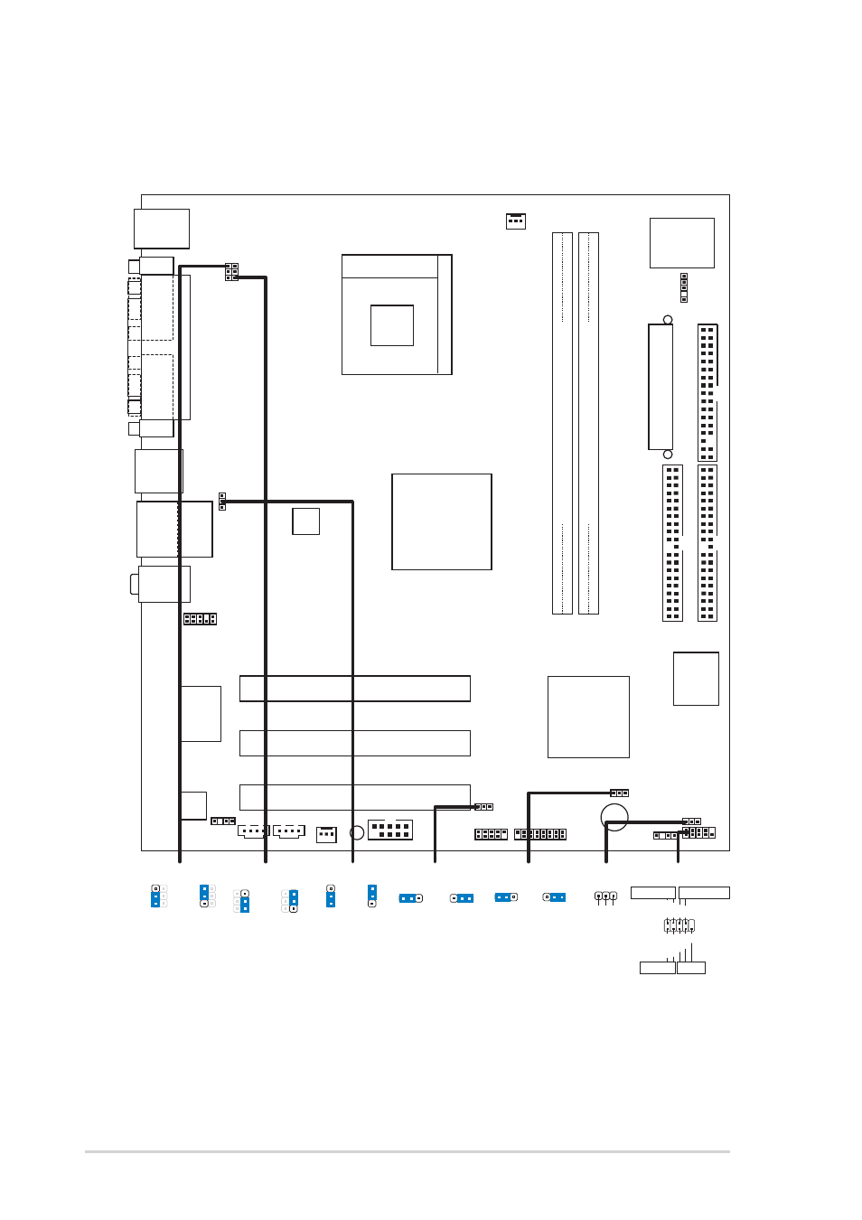
1.5
Motherboard overview
1.5.1 Motherboard layout
F_PANEL
FLOPPY1
SEC_IDE
PRI_ IDE
Intel
82801DB
ICH4
P4BP-MX 2.0
3Mbit
Firmware
Hub
ATX12V1
Intel
82845GV
Memory
Controller
Hub
AUX
CPU_FAN
CD
CHA_FAN
Super
I/O
GAME1
Socket 478
PCI1
Audio
Codec
Below:Mic In
Center:Line Out
Top:Line In
CHASSIS
COM2
PCI2
PCI3
P
ARALLEL
PORT
COM1
VGA
PS/2KBMS
T: Mouse
B: Keyboard
USB12
A
TX Power Connector
PLED
IR_CON
USB56
FP_AUDIO
DDR DIMM2 (64/72 bit, 184-pin module)
2 3
DDR DIMM1 (64/72 bit, 184-pin module)
0 1
USBPWR_56
BUZZ
R
TL8100C
KBPWR
USBPWR_34
USBPWR_12
SB_PWR
Top:
RJ-45
Bottom:
USB34
SPDIF_OUT
CLRTC
2 3
2
1
+5V
(Default)
+5VSB
USBPWR_56
USBPWR_12
1
2
3
2
(Default)
+5V
+5VSB
USBPWR_34
1
2
3
2
(Default)
+5V
+5VSB
KBPWR
1
2
3
2
(Default)
+5V
+5VSB
PLED1
PLED+
1
NC
PLED-
F_PANEL
PLED-
PWR
PLED+
Ground
GND
Reset
IDE_LED+
IDE_LED-
IDE_LED
Reset
Power LED
Power Button
NC
1 2
CLRTC
Normal
Clear CMOS
(Default)
2 3