Multichannel Systems TC01-TC02 Manual User Manual
Page 12
Temperature Controller TC01/02 Manual
8
3.2 Setting Up and Connecting the TC01/02
Provide a power supply in the immediate vicinity of the installation site.
1. Place the TC01/02 on a dry and stable surface, where the air can circulate freely and the device
is not exposed to direct sunlight.
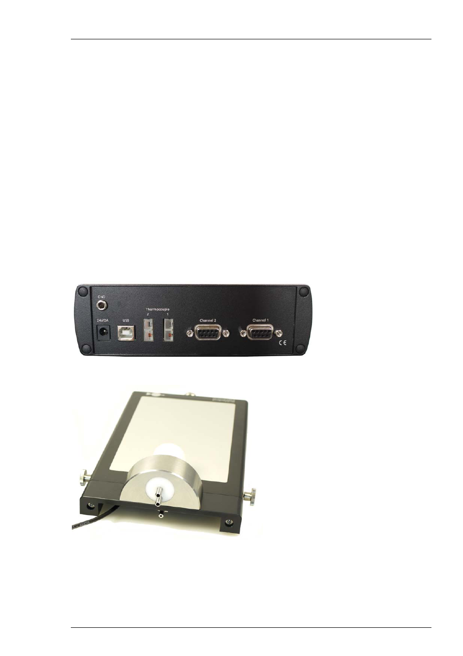
2. Plug the external power supply cable into the supply power input socket on the rear panel
of the TC01/02.
3. Connect the external power supply to the power outlet.
4. Optional, for recording temperature curves or remote control: Connect the USB cable to a free
USB port of the data acquisition computer.
5. Connect the TC01/02 to the heating element. Use the cable that is delivered with the heating
system or use a custom cable. The cable is plugged into the female D-Sub9 socket. (Channel 1
and Channel 2, if you have a TC02). See also chapter "D-Sub9 Pin Assignment" in the Appendix.
6. Use of OP Table: Connect the TC01/02 to the heating element of the heating plate. Use the cable
that is delivered with the heating system or use a custom cable. The cable is plugged into the
female D-Sub9 socket labeled with "Channel 1". Connect the TC01/02 to the rectal thermometer.
Use the provided cable, and connect the rectal thermometer via the thermocouple connector
(type T) to the socket labeled with "Thermocouple 1".