Multichannel Systems PPS2 Manual User Manual
Page 15
PPS2 Manual
13
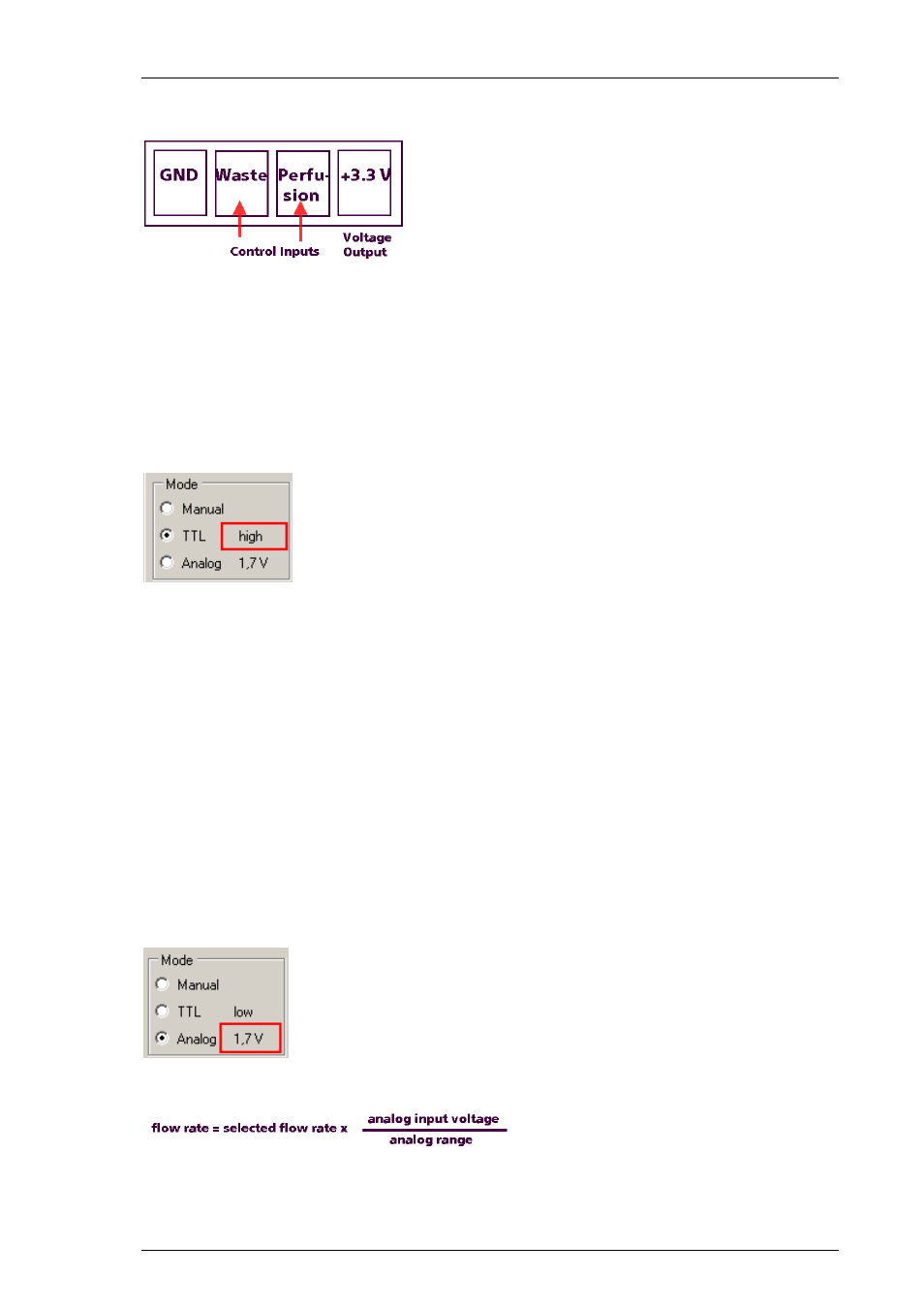
When looking directly to the rear panel of the PPS2 the pin layout of the digital and analog
inputs are as shown on the picture.
Connect either a TTL or an analog output device to the respective inputs and select the
desired control mode in the PPS2 software. In sum (digital and analog input), the maximum
load current for the voltage output (+3.3 V) is 100 mA.
Digital Control
Connect, for example a stimulation generator STG4000, to the “Ground” and “Control
Input(s)” of the digital input on the rear panel. The “Voltage Output” is not needed.
The status of the TTL inputs are displayed in the “Mode” window. If nothing is connected
to the TTL inputs the status is low.
TTL input low (
+0.4 V) pump off.
TTL input high (
+1.5 V ) pump on.
As long as the status of the TTL input is high, the respective pump will run at the speed
selected in PPS2 software. The maximum voltage for the TTL input is +5.5 V.
Analog Control
With the analog control, it is possible not only to start and stop the pump by an external
device, but also the pump speed. Connect an adjustable voltage source, for example a
potentiometer to the “Ground” and “Control Input(s)” of the analog input on the rear panel.
The pin layout of the analog input is the same as for the digital input when looking directly
to the rear panel of the PPS2. If nothing is connected to the analog inputs the status is 0.0 V.
The maximum voltage for the analog input is +10.3 V.
The current voltage level on the analog inputs is displayed in the “Mode” window. The analog
range is by default +5.0 V, as stated in the dialog “More”.
The resulting fluid flow of the pumps can be calculated by the following equation:
Example:
Selected flow rate 5ml/min x (analog input voltage 10 V / analog range 5 V)=10 ml/min.